


FUEL SYSTEM
Engine Control Linkage
2006-2010 Turf/Carryall 272/472 and XRT 1200/1200 SE Maintenance and Service Manual
Page 14-7
14
Accelerator Rod Installation and Adjustment
1. Turn the key switch to OFF and remove the key. Place the Forward/Reverse handle in the NEUTRAL
position. Chock the wheels.
2. Adjust accelerator pedal position.
See Accelerator Pedal Adjustment, Section 5, Page 5-6.
3. Install the ball joint on the ball stud at the accelerator pedal
.
4. Remove the air intake hose from the carburetor.
5. Remove the electrical box screw and cover.
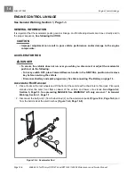
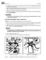
6. With the ball joint jam nuts (3) loose
, adjust the length of the accelerator rod
so the indicated cam edge is parallel with the edge of the electrical component box
See following CAUTION.
ý
CAUTION
• After accelerator rod adjustment, make sure that approximately the same number of threads
are exposed at each end of the accelerator rod.
7. Install the accelerator rod on the bell crank ball joint on the electrical component box
See following CAUTION and NOTE
.
ý
CAUTION
• Inspect the limit switch inside the electrical box. If the limit switch lever is bent, replace the
switch.
NOTE:
Use the inside hole location, or hole closest to the bell crank shaft as shown.
8. Confirm proper accelerator rod operation before tightening jam nuts:
8.1. The carburetor throttle should begin to move when the pedal is pressed approximately 8° to 12°.
9. Tighten the jam nuts against the ball joints at each end of the accelerator rod, accelerator ball joint first,
while holding the ball joints with pliers.
10. Check rod adjustment for proper switch activation.
11. Adjust the engine RPM setting.
See Engine RPM Adjustment on page 14-10.
12. Install the electrical component box cover and tighten retaining screw to 18 in-lb (2.0 N·m).
13. Install the air intake hose onto the carburetor.
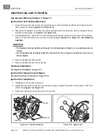
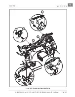
GOVERNOR CABLE
Governor Cable Removal
1. Turn the key switch OFF and remove the key. Place the Forward/Reverse handle in the NEUTRAL posi-
tion. Chock the wheels
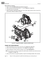
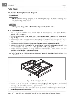
2. Remove the governor cable (8) from the engine bracket (19) and lift the Z-shaped cable end from the car-
buretor throttle bracket
3. Remove the cable from engine bracket (18) and lift the Z-shaped cable end from the governor bracket.
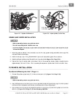
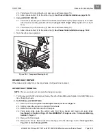
Governor Cable Installation and Adjustment
1. Install the Z-shaped end into the governor bracket (18) and push cable down into bracket slot to secure.
Содержание CARRYALL 272
Страница 2: ......
Страница 14: ......
Страница 18: ...1...
Страница 52: ...5...
Страница 90: ...6...
Страница 110: ...7...
Страница 112: ...8...
Страница 128: ...10...
Страница 170: ...11...
Страница 224: ...13...
Страница 284: ...16...
Страница 302: ...17...
Страница 308: ......
Страница 309: ...Club Car R NOTES...
Страница 310: ...Club Car R NOTES...
Страница 311: ......


