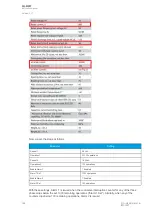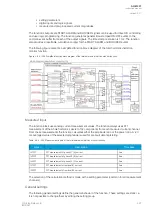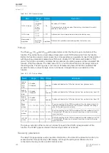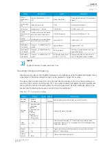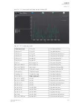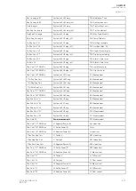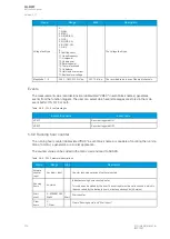
Signal
Description
Signal
Description
Lx PF
Lx power factor (L1, L2, L3)
Curve x Input
Input of Curve x (1, 2, 3, 4)
POW1 3PH
Apparent power
(S)
Three-phase apparent
power
Curve x Output
Output of Curve x (1, 2, 3, 4)
POW1 3PH
Apparent power
(S MVA)
Three-phase apparent
power in megavolt-amperes
Enablefbasedfunctions(VT1)
Enable frequency-based functions
POW1 3PH Active
power (P)
Three-phase active power
Track.sys.f.
Tracked system frequency
POW1 3PH Active
power (P MW)
Three-phase active power
in megawatts
Sampl.f. used
Used sample frequency
POW1 3PH
Reactive power
(Q)
Three-phase reactive power Tr f CH x
Tracked frequency (channels A, B, C)
POW1 3PH
Reactive power (Q
MVar)
Three-phase reactive power
in megavars
Alg f Fast
Fast frequency algorithm
POW1 3PH
Tan(phi)
Three-phase tangent phi
Alg f avg
Average frequency algorithm
POW1 3PH
Cos(phi)
Three-phase cosine phi
Frequency based
protections blocked
When true ("1"), all frequency-based
protections are blocked.
3PH PF
Three-phase power factor
f atm. Protections (when not
measurable returns to
nominal)
Frequency at the moment. If the system
nominal is set to 50 Hz, this will show "50
Hz".
Neutral
conductance G
(Pri)
Primary neutral
conductance
f atm. Display (when not
measurable is 0 Hz)
Frequency at the moment. If the frequency
is not measurable, this will show "0 Hz".
Neutral
susceptance B
(Pri)
Primary neutral
susceptance
f meas qlty
Quality of tracked frequency
Neutral
admittance Y (Pri)
Primary neutral admittance
f meas from
Indicates which of the three voltage or
current channel frequencies is used by the
relay.
Neutral
admittance Y
(Ang)
Neutral admittace angle
SS1.meas.frqs
Synchrocheck – the measured frequency
from voltage channel 1
I01 Resistive
component (Pri)
Primary resistive
component I01
SS2.meas.frqs
Synchrocheck – the measured frequency
from voltage channel 2
I01 Capacitive
component (Pri)
Primary capacitive
component I01
Enable f based functions
Status of this signal is active when
frequency-based protection functions are
enabled.
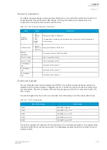
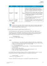
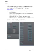
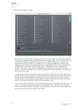
Table. 5.6.6 - 316. Digital recording channels – Binary signals.
Signal
Description
Signal
Description
DIx
Digital input 1...11
Timer x Output
Output of Timer 1...10
Open/close
control
buttons
Active if buttons I or 0 in the unit's
front panel are pressed.
Internal Relay Fault active
If the unit has an internal fault, this signal
is active.
Status
PushButton x
On
Status of Push Button 1...12 is ON
(Protection, control and
monitoring event signals)
(see the individual function description for
the specific outputs)
A
AQ
Q-M257
-M257
Instruction manual
Version: 2.07
398
© Arcteq Relays Ltd
IM00021
Содержание AQ-M257
Страница 1: ...AQ M257 Motor protection IED Instruction manual...
Страница 2: ......
Страница 449: ...Figure 7 3 221 Example block scheme A AQ Q M257 M257 Instruction manual Version 2 07 Arcteq Relays Ltd IM00021 447...
Страница 470: ...Figure 8 14 243 Device installation A AQ Q M257 M257 Instruction manual Version 2 07 468 Arcteq Relays Ltd IM00021...

