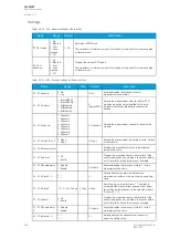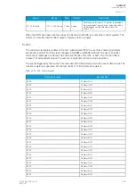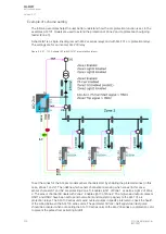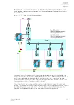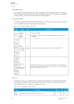
Table. 5.4.29 - 239. Calculations of the transformer differential function.
Name
Description
L1Bias
The calculated phase L1 bias current
L2Bias
The calculated phase L2 bias current
L3Bias
The calculated phase L3 bias current
L1Diff
The calculated phase L1 differential current
L2Diff
The calculated phase L2 differential current
L3Diff
The calculated phase L3 differential current
L1Char
The calculated phase L1 maximum differential current allowed with current bias level
L2Char
The calculated phase L1 maximum differential current allowed with current bias level
L3Char
The calculated phase L1 maximum differential current allowed with current bias level
HV I0d> Bias current
The calculated HV side restricted earth fault bias current
HV I0d> Diff current
The calculated HV side restricted earth fault differential current
HV I0d> Char current
The calculated HV side restricted earth fault differential current allowed with current bias level
LV I0d> Bias current
The calculated LV side restricted earth fault bias current
LV I0d> Diff current
The calculated LV side restricted earth fault differential current
LV I0d> Char current
The calculated LV side restricted earth fault differential current allowed with current bias level
Table. 5.4.29 - 240. Output signals of the transformer differential function.
Name
Description
Idb> Bias Trip
The TRIP output signal from the biased differential stage
Idi> Nobias Trip
The TRIP output signal from the non-biased and non-blocked differential stage
Idb> Bias Blocked
The BLOCKED output from the biased differential stage (external blocking)
Idi> Bias Blocked
The BLOCKED output from the non-biased and non-blocked differential stage (external blocking)
Idb> 2
nd
harm block on
The output of the 2
nd
harmonic activation signal
Idb> 5
th
harm block on
The output of the 5
th
harmonic activation signal
HV I0d> Trip
The TRIP output signal from the biased restricted earth fault differential stage on the HV side
HV I0d> Trip
The BLOCKED output signal from the biased restricted earth fault differential stage on the HV side
LV I0d> Trip
The TRIP output signal from the biased restricted earth fault differential stage on the LV side
LV I0d> Trip
The BLOCKED output signal from the biased restricted earth fault differential stage on the LV side
Events and registers
The transformer differential function (abbreviated "DIF" in event block names) generates events from
internal status changes. The data register is available, based on the changes in the tripping events.
Table. 5.4.29 - 241. Event messages.
Event block name
Event names
DIF1
Idb> Trip ON
DIF1
Idb> Trip OFF
DIF1
Idb> Blocked (ext) ON
A
AQ
Q-M257
-M257
Instruction manual
Version: 2.07
© Arcteq Relays Ltd
IM00021
319
Содержание AQ-M257
Страница 1: ...AQ M257 Motor protection IED Instruction manual...
Страница 2: ......
Страница 449: ...Figure 7 3 221 Example block scheme A AQ Q M257 M257 Instruction manual Version 2 07 Arcteq Relays Ltd IM00021 447...
Страница 470: ...Figure 8 14 243 Device installation A AQ Q M257 M257 Instruction manual Version 2 07 468 Arcteq Relays Ltd IM00021...

