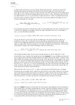
• Turnpoint 1: double the neutral current CT nominal primary to transformer nominal current
ratio
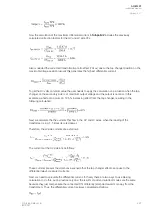
• Slope 1: calculate the maximum single-phase through fault overcurrent to nominal ratio and
used biasing mode ratio
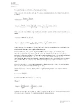
• Turnpoint2: set to maximum accuracy limit factor to transformer nominal ratio of the neutral
point CT (typically 5 or 10); if the single-phase overcurrent fault exceeds this value, set
Turnpoint 2 to that value
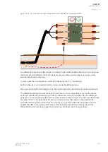
• Slope 2: set the maximum restraint calculation mode to 100 % and the average mode to 200
%.
Blockings from harmonics (2
nd
and 5
th
)
In transformer protection harmonics are always present in energizing situations: they are generated by
the high current in the transformer inductances when the coils are energized. They are also preent in
the currents during overfluxing and overvoltage situations. Energizing situations generate even
harmonics: the 2
nd
harmonic is the most commonly used harmonic in inrush blocking. Overvoltage
(and overexcitation) situations generate odd harmonics: the 5
th
harmonic is mainly used for blocking
(the 3
rd
harmonic is also present in Y windings but absent in delta windings which is why the 5
th
harmonic has been chosen for overfluxing and excitation detection). In this chapter 'blocking' refers to
the Idb> (the biased differential) stage and it has both these blocking (2
nd
and 5
th
) applied internally. If
the Idi> stage (the non-biased differential) needs to be blocked, external blocking must be used.
2
nd
harmonic for magnetizing inrush blocking (principle and usage)
When the primary side of a power transformer is energized (secondary side open), the transformer
acts as a simple inductance. During normal operation the flux produced in the transformer core lags
behind the fed voltage by 1.58 radians (90 degrees). This means that when the voltage is in zero
crossing, the steady state value of the flux is in its negative or positive maximum value. In
energizing situations there is no flux available at the instant the winding is energized because there is
no (live) magnetic flux linked to the transformer core prior to switching on the supply (however,
remanence flux may still exist). The flux reaches its steady state operation some time after energization
(depends on the transformer's properties such as its size, its R/X ratio, etc.). In practice this means that
the flux in the transformer core starts from zero, as does the voltage in the winding; when energizing
the transformer's primary side, the flux ends up 90 degrees behind the winding voltage and the system
is in a steady state.
This start-up transition in the transformer has the effect of making the flux value be double the nominal
flux value in the first half of the cycle after energization. The transformer core is generally saturated just
above the steady state value of the flux and because of this the transformer core is decreasingly
saturated during the transition time. During this saturation time the transformer's primary side draws a
very high current with a heavy amount of even harmonics (the highest being the 2
nd
). This current is
called the "magnetizing inrush current in transformer". The inrush current can be up to ten times higher
than the nominal rated current of a transformer. The energizing characteristics of a transformer depend
on the ratings of the transformer as well on the transformer's design (limb constructions, etc.).
The differential relay sees the energization current as a differential current since it only flows through
the primary side winding only. The saturation of the transformer core generates the 2
nd
harmonic
component which can be used to block the biased sensitive differential stage during energization.
A
AQ
Q-M257
-M257
Instruction manual
Version: 2.07
308
© Arcteq Relays Ltd
IM00021
Содержание AQ-M257
Страница 1: ...AQ M257 Motor protection IED Instruction manual...
Страница 2: ......
Страница 449: ...Figure 7 3 221 Example block scheme A AQ Q M257 M257 Instruction manual Version 2 07 Arcteq Relays Ltd IM00021 447...
Страница 470: ...Figure 8 14 243 Device installation A AQ Q M257 M257 Instruction manual Version 2 07 468 Arcteq Relays Ltd IM00021...


