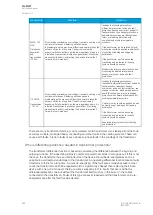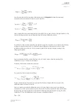
This gives the absolute difference in the measured currents.
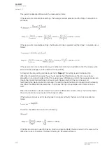
If the user wants more sensitive settings, the Average mode is selected and the Slope 1 calculation is
as follows:
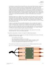
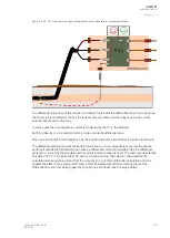
If the user wants more stable settings, the Maximum mode is selected and the Slope 1 calculation is as
follows:
If the user wants to be on the safe side, yet another safety margin (in addition to the 5 % already in the
base sensitivity settings) can be added to ensure stability.
At this point the only setting still missing is that of SSlope 2.
lope 2. This setting is used for biasing the
differential characteristics against heavy faults outside the differential zone that can cause heavy
saturation on one or both sides of the CTs causing heavy differential current in the measurements even
though the transformer itself does not have a fault. Please note that if there is a heavy end
fault causing the biasing current to increase, this setting should not be set to maximum as the biasing
may block the differential characteristics. This makes the trip not applicable even if there is an end
fault.
When the transformer is fed from the HV side and the differential current is direct, the fault that feeds
the end current can be accounted in the Slope 2 setting.
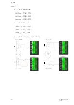
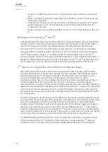
If the Average mode is used for biasing (due to a single end fault), the bias current is calculated as
follows:
Therefore, the differential current is the following:
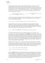
If the Maximum mode is used for biasing (due to a single end fault), the bias current is the same as the
differential current. Therefore, the Slope 2 setting is calculated as follows:
A
AQ
Q-M257
-M257
Instruction manual
Version: 2.07
298
© Arcteq Relays Ltd
IM00021
Содержание AQ-M257
Страница 1: ...AQ M257 Motor protection IED Instruction manual...
Страница 2: ......
Страница 449: ...Figure 7 3 221 Example block scheme A AQ Q M257 M257 Instruction manual Version 2 07 Arcteq Relays Ltd IM00021 447...
Страница 470: ...Figure 8 14 243 Device installation A AQ Q M257 M257 Instruction manual Version 2 07 468 Arcteq Relays Ltd IM00021...

