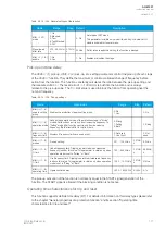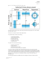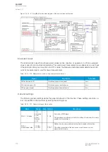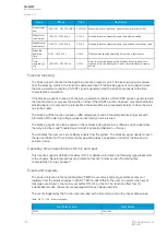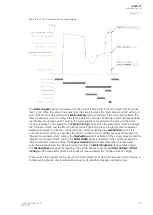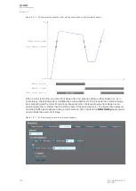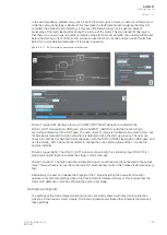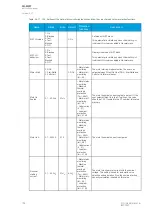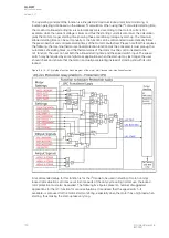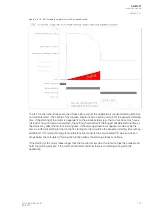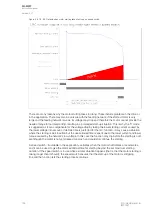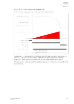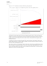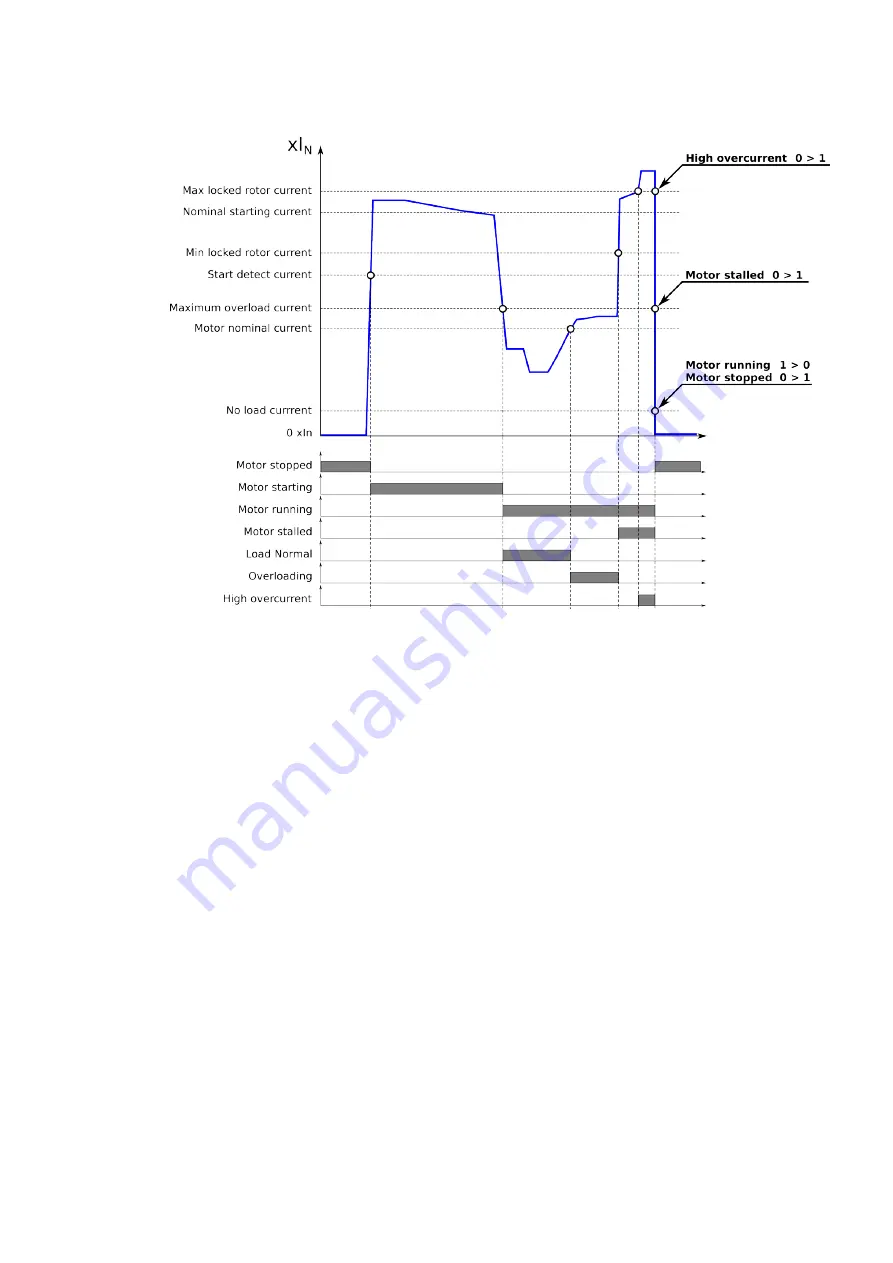
Figure. 5.4.17 - 93. Activation of the function's outputs.
The
Mo
Mottor st
or stopped
opped signal is activated when the current is below the “No load current” limit for longer
than 10 ms. When the current increases from this status to above the “Start detect current” setting, a
start of the motor is detected and the
Mo
Mottor star
or starting
ting signal is activated. If the current stays below the
“Max locked rotor current” setting, the start-up situation continues. When the current decreases below
the “Maximum overload current” setting, the start situation is considered to be over and the motor
running, resulting in the activation of the
Mo
Mottor running
or running signal. When the measured current is between
the “No load current” and the "Motor nominal current" (including the service factor and the ambient
temperature factor), the load is considered to be normal, activating the
LLoad Normal
oad Normal signal. If the
current then starts rising, and exceeds the “Motor nominal current” setting but does not exceed the
“Maximum overload current” setting, the
Ov
Overloading
erloading signal is activated. If the current does exceed the
“Maximum overload current” setting, the
Mo
Mottor stalled
or stalled signal is activated. If the current exceeds the
“Max locked rotor current” setting, the
Hig
High o
h ovver
ercurr
current
ent signal is activated. When the measured
current decreases below the “No load current” setting, the
Mo
Mottor st
or stopped
opped signal is activated again.
The
Missing pha
Missing phase
se signal is activated only if one of the phases is lost during Mo
Mottor star
or starting
ting or Mo
Mottor
or
running
running and the measured current in that phase is reduced below the “No load current” setting.
These motor status signals can be used in the motor protection scheme to block overcurrent stages, to
change setting groups, and to release blockings (e.g if something happens during start-up).
A
AQ
Q-M257
-M257
Instruction manual
Version: 2.07
© Arcteq Relays Ltd
IM00021
181
Содержание AQ-M257
Страница 1: ...AQ M257 Motor protection IED Instruction manual...
Страница 2: ......
Страница 449: ...Figure 7 3 221 Example block scheme A AQ Q M257 M257 Instruction manual Version 2 07 Arcteq Relays Ltd IM00021 447...
Страница 470: ...Figure 8 14 243 Device installation A AQ Q M257 M257 Instruction manual Version 2 07 468 Arcteq Relays Ltd IM00021...


