Name
Range
Step Default
Description
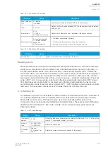
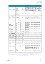
Select
record
trigger
0: TRIP signal
1: START signal
2: START and TRIP signals
-
0: TRIP
signal
Selects what triggers the fault register recording: the selected
function's TRIP signal, its START signal, or either one.
Recorded
fault
value
- 1000 000.00…1 000
000.00
0.01
-
Displays the recorded measurement value at the time of the
selected fault register trigger.
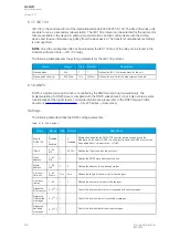
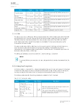
6.3 Real-time measurements to communication
With the
Real-time signals to communication menu the user can report to SCADA measurements that
are not normally available in the communication protocols mapping. Up to eight (8) magnitudes can be
selected. The recorded value can be either a per-unit value or a primary value (set by the user).
Measurable values
Function block uses analog current and voltage measurement values. The relay uses these values as
the basis when it calculates the primary and secondary values of currents, voltages, powers,
impedances and other values.
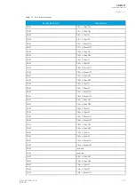
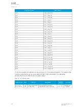
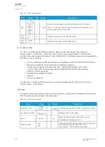
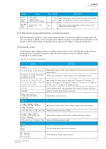
Table. 6.3 - 362. Available measured values.
Signals
Description
Currents
IL1 (ff), IL2 (ff), IL3 (ff), I01 (ff), I02 (ff)
Fundamental frequency (RMS) current measurement values of phase currents and
residual currents.
IL1 (TRMS), IL2 (TRMS), IL3 (TRMS),
I01 (TRMS), I02 (TRMS)
TRMS current measurement values of phase currents and residual currents.
IL1, IL2, IL3, I01, I02 & 2
nd
h., 3
rd
h.,
4
th
h., 5
th
h., 7
th
h., 9
th
h., 11
th
h., 13
th
h., 15
th
h., 17
th
h., 19
th
h.
Magnitudes of the phase current components: 2
nd
harmonic, 3
rd
harmonic, 4
th
harmonic, 5
th
harmonic 7
th
, harmonic 9
th
, harmonic 11
th
, harmonic 13
th
, harmonic
15
th
, harmonic 17
th
, harmonic 19
th
harmonic current.
I1, I2, I0Z
Positive sequence current, negative sequence current and zero sequence current.
I0CalcMag
Residual current calculated from phase currents.
IL1Ang, IL2Ang, IL3Ang,
I01Ang, I02Ang, I0CalcAng
I1Ang, I2Ang
Angles of each measured current.
Voltages
UL1Mag, UL2Mag, UL3Mag,
UL12Mag, UL23Mag, UL31Mag,
U0Mag, U0CalcMag
Magnitudes of phase voltages, phase-to-phase voltages and residual voltages.
U1 Pos.seq V mag, U2 Neg.seq V mag
Positive and negative sequence voltages.
UL1Ang, UL2Ang, UL3Ang,
UL12Ang, UL23Ang, UL31Ang,
U0Ang, U0CalcAng
Angles of phase voltages, phase-to-phase voltages and residual voltages.
U1 Pos.seq V Ang, U2 Neg.seq V Ang
Positive and negative sequence angles.
Powers
S3PH
P3PH
Q3PH
Three-phase apparent, active and reactive power.
SL1, SL2, SL3,
PL1, PL2, PL3,
QL1, QL2, QL3
Phase apparent, active and reactive powers.
A
AQ
Q-M257
-M257
Instruction manual
Version: 2.07
© Arcteq Relays Ltd
IM00021
435
Содержание AQ-M257
Страница 1: ...AQ M257 Motor protection IED Instruction manual...
Страница 2: ......
Страница 449: ...Figure 7 3 221 Example block scheme A AQ Q M257 M257 Instruction manual Version 2 07 Arcteq Relays Ltd IM00021 447...
Страница 470: ...Figure 8 14 243 Device installation A AQ Q M257 M257 Instruction manual Version 2 07 468 Arcteq Relays Ltd IM00021...

