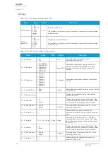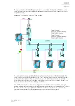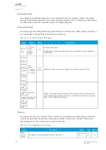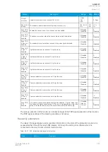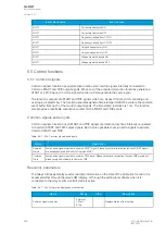
Table. 5.4.31 - 246. Output signals of the IArc>/I0Arc> function.
Outputs
Activation condition
Channel 1 Light In
Channel 2 Light In
Channel 3 Light In
Channel 4 Light In
The arc protection card's sensor channel detects light.
Channel 1 Pressure In
Channel 2 Pressure In
Channel 3 Pressure In
Channel 4 Pressure In
The arc protection card's sensor channel detects pressure.
ARC Binary input signal
The arc protection card's binary input is energized.
I/I0 Arc> Ph. curr.
START
I/I0 Arc> Res. curr.
START
The measured phase current or the residual current is over the set limit.
I/I0 Arc> Ph. curr.
BLOCKED
I/I0 Arc> Res. curr.
BLOCKED
The phase current or the residual current measurement is blocked by an input.
I/I0 Arc> Zone 1 TRIP
I/I0 Arc> Zone 2 TRIP
I/I0 Arc> Zone 3 TRIP
I/I0 Arc> Zone 4 TRIP
All required conditions for tripping the zone are met (light OR light and current).
I/I0 Arc> Zone 1
BLOCKED
I/I0 Arc> Zone 2
BLOCKED
I/I0 Arc> Zone 3
BLOCKED
I/I0 Arc> Zone 4
BLOCKED
All required conditions for tripping the zone are met (light OR light and current) but the tripping is
blocked by an input.
I/I0 Arc> S1 Sensor fault
I/I0 Arc> S2 Sensor fault
I/I0 Arc> S3 Sensor fault
I/I0 Arc> S4 Sensor fault
The detected number of sensors in the channel does not match the settings.
I/I0 Arc> IO unit fault
The number of connected AQ-100 series units does not match the number of units set in the
settings.
The operational logic consists of the following:
• input magnitude selection
• input magnitude processing
• threshold comparator
• block signal check
• output processing.
The inputs for the function are the following:
• operating mode selections
• setting parameters
• digital inputs and logic signals
• measured and pre-processed current magnitudes.
The function's outputs are TRIP, BLOCKED, light sensing etc. signals which can be used for direct I/O
controlling and user logic programming. The function generates general time-stamped ON/OFF events
to the common event buffer from each of the 26 output signals. The time stamp resolution is 1 ms. The
function also a resettable cumulative counter for the TRIP and BLOCKED events for each zone.
A
AQ
Q-M257
-M257
Instruction manual
Version: 2.07
© Arcteq Relays Ltd
IM00021
329
Содержание AQ-M257
Страница 1: ...AQ M257 Motor protection IED Instruction manual...
Страница 2: ......
Страница 449: ...Figure 7 3 221 Example block scheme A AQ Q M257 M257 Instruction manual Version 2 07 Arcteq Relays Ltd IM00021 447...
Страница 470: ...Figure 8 14 243 Device installation A AQ Q M257 M257 Instruction manual Version 2 07 468 Arcteq Relays Ltd IM00021...


