Name
Range
Step
Default
Function
Description
LV side lead
or lag HV
0: Lead
1: Lag
-
0: Lead
- transformer
status
monitoring
- transformer
differential
The selection of whether the LV side leads or lags the
HV side. The selection is visible only if the option
"Manual set" is selected for the vector group setting.
HV-LV side
phase angle
0.0...360.00deg 0.1deg
0.0deg
- transformer
status
monitoring
- transformer
differential
The angle correction factor for HV/LV sides, looked
from the HV side. E.g. if the transformer is Dy1, this is
set to 30 degrees. The selection is visible only if the
option "Manual set" is selected for the vector group
setting.
HV-LV side
mag
correction
0.0...100.0×I
n
0.1×I
n
0.0×I
n
- transformer
status
monitoring
- transformer
differential
The magnitude correction for the HV-LV side currents
(in p.u.), if the currents are not directly matched
through the calculations of the nominal values. The
selection is visible only if the option "Manual set" for
the vector group setting.
Check
online HV-LV
configuration
0: -
1: Check
-
0: -
- transformer
status
monitoring
- transformer
differential
The selection of whether or not the function checks
the current going through the transformer and then
compares it to the settings. For this to work, the
transformer needs to have a current flowing on both
sides and "see" no faults. The selection is visible only if
the option "Manual set" is selected for the vector
group setting.
Enable I0d>
(REF) HV
side
0: Disabled
1: Enabled
-
0:
Disabled
- transformer
status
monitoring
- transformer
differential
The selection of whether the restricted earth fault
stage on the HV side is enabled or disabled.
HV side
starpoint
meas.
0: IO1
1: IO2
-
0: IO1
- transformer
status
monitoring
- transformer
differential
The selection of the starpoint measurement channel
for the restricted earth fault protection on the HV side.
This setting is only visible if the option "Enabled" is
selected for the "Enable I0d> (REF) HV side" setting.
Enable I0d>
(REF) LV
side
0: Disabled
1: Enabled
-
0:
Disabled
- transformer
status
monitoring
- transformer
differential
The selection of whether the restricted earth fault
stage on the LV side is enabled or disabled.
LV side
starpint
meas.
0: IO1
1: IO2
-
0: IO1
- transformer
status
monitoring
- transformer
differential
The selection of the starpoint measurement channel
for the restricted earth fault protection on the LV side.
This setting is only visible if the option "Enabled" is
selected for the "Enable I0d> (REF) LV side" setting.
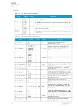
Table. 5.4.29 - 238. Settings for the operating characteristics.
Name
Range
Step
Default
Description
Differential
calculation
mode
0: Add
1: Subtract
-
1:
Subtract
The calculation mode of the differential current. The mode selection
depends on the CTs' installation direction and the desired current
directions. If the current flow on both sides is in the same direction,
the differential current is subtracted. If the current flows are in the
opposite directions, the differential current is added.
Bias
calculation
mode
0: Average
1: Maximum
-
0:
Average
The calculation mode of the biasing current. With the average mode
the operation may be set to be more sensitive. With the maximum
mode the bias is always higher and thus provides a more stable
operation.
Idb> Pick-
up
0.01…100.00%
0.01%
10.00%
The base sensitivity for the differential characteristics.
Turnpoint
1
0.01…50.00×I
n
0.01×I
n
1.00×I
n
Turnpoint 1 for the differential characteristics.
Slope 1
0.01…250.00%
0.01%
10.00%
Slope 1 for the differential characteristics.
A
AQ
Q-M257
-M257
Instruction manual
Version: 2.07
© Arcteq Relays Ltd
IM00021
317
Содержание AQ-M257
Страница 1: ...AQ M257 Motor protection IED Instruction manual...
Страница 2: ......
Страница 449: ...Figure 7 3 221 Example block scheme A AQ Q M257 M257 Instruction manual Version 2 07 Arcteq Relays Ltd IM00021 447...
Страница 470: ...Figure 8 14 243 Device installation A AQ Q M257 M257 Instruction manual Version 2 07 468 Arcteq Relays Ltd IM00021...


