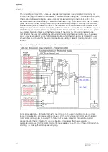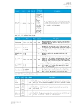
The operating principle of the function is either definite maximum locked rotor time monitoring, or
inverse operating time based on the allowed
I
2
t calculation. When using the I
2
t-calculated starting time,
the maximum allowed starting time is automatically scaled according to the motor's current. For
example, when the network voltage is lower and thus the starting current is also lower, the calculation
gives the motor a longer starting time knowing these conditions prolong any start-up. The maximum
allowed starting time can be set manually, or the function can be commanded to automatically follow
the prescribed hot and cold safe stalling times of the motor manufacturer. Please note that this requires
the following: the machine thermal overload protection function must be activated, it must pick-up the
automatic safe stalling times, and the thermal status of the motor must be communicated to the
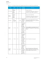
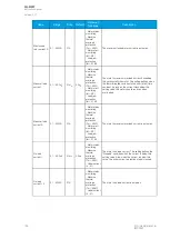
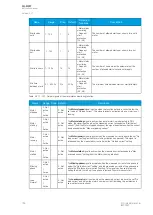
Ist> function. The user can set both the allowed starting time and the speed switch input. The speed
switch may be required by some high-mass applications when the start-up may last longer; the user
should check and ensure that the motor is actually accelerating instead of standing still with its rotor
locked.
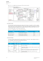
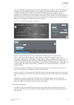
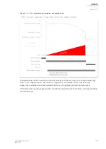
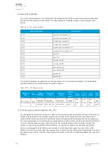
Figure. 5.4.18 - 97. Simplified function block diagram of the motor start/ locked rotor monitoring function.
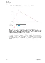
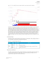
A recommended setup for this function is for the I
2
t mode to be used in starting; if motor running/
locked rotor situations at times occur in some parts of the duty cycle during normal use, the locked
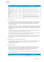
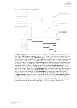
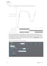
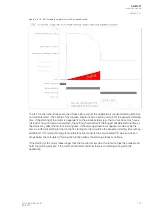
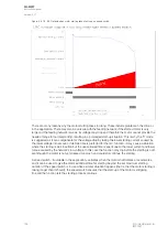
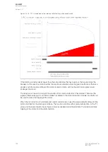
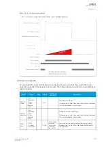
rotor protection must also be applied. The following five figures present a number of suggested
applications for the Ist> function for various situations. It is advised that the speed switch –if
available– is also used for the motor start monitoring, especially when the motor has a high load when
starting, thus making the start-up take very long.
A
AQ
Q-M257
-M257
Instruction manual
Version: 2.07
190
© Arcteq Relays Ltd
IM00021
Содержание AQ-M257
Страница 1: ...AQ M257 Motor protection IED Instruction manual...
Страница 2: ......
Страница 449: ...Figure 7 3 221 Example block scheme A AQ Q M257 M257 Instruction manual Version 2 07 Arcteq Relays Ltd IM00021 447...
Страница 470: ...Figure 8 14 243 Device installation A AQ Q M257 M257 Instruction manual Version 2 07 468 Arcteq Relays Ltd IM00021...

