Application example
This chapter presents an application example of how to set the disturbance recorder and analyze its
output. The recorder is configured by using the setting tool software or relay HMI, and the results are
analyzed with the AQviewer software (is automatically downloaded and installed with
AQtivate). Registered users can download the latest tools from the Arcteq website
In this example, we want the recordings to be made according to the following specifications:
• the recording length is 6.0 s
• the sample rate is 64 s/c (therefore, with a 50 Hz system frequency a sample is taken every
312.5 µs)
• the analog channels 1...8 are used
• digital channels are tracked every 5 ms
• the first activation of the overcurrent stage trip (I> TRIP) triggers the recorder
• the pre-triggering time is 5 (ie. how long is recorded before the I> TRIP signal) and the post-
triggering time is 1 s
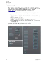
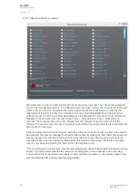
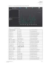
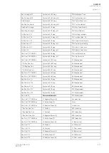
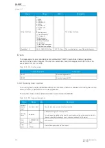
The image below shows how these settings are placed in the setting tool.
Figure. 5.6.6 - 209. Disturbance recorder settings.
A
AQ
Q-M257
-M257
Instruction manual
Version: 2.07
402
© Arcteq Relays Ltd
IM00021
Содержание AQ-M257
Страница 1: ...AQ M257 Motor protection IED Instruction manual...
Страница 2: ......
Страница 449: ...Figure 7 3 221 Example block scheme A AQ Q M257 M257 Instruction manual Version 2 07 Arcteq Relays Ltd IM00021 447...
Страница 470: ...Figure 8 14 243 Device installation A AQ Q M257 M257 Instruction manual Version 2 07 468 Arcteq Relays Ltd IM00021...

