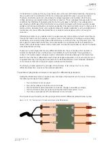
The differential protection area is the area between the current transformers. This is called the
differential zone which means that the currents going in from one side must come out from the other
side. This is true whether the signal is scaled higher or lower, or whether the phase angle is shifted.
Unless both side currents match there is a problem within the protected zone which either blocks or
keeps the current inside the zone.
The image below shows what a typical transformer name plate looks like, what data it includes and
what to do with it.
Figure. 5.4.29 - 146. Transformer name plate data.
According to the data on this example name plate, this transformer is designed for three-phase
usage and therefore it has two windings. The nominal power of the transformer is 2 MVA. Its vector
group is Yd1: this means that the high-voltage side is connected to the Y and the low-voltage side to
the delta, resulting in the LV side having a 30-degree lag in relation to the HV side. Additionally, the HV
side's nominal voltage is 10 kV and its amperage is 116 A, on the LV side the nominal voltage is 1kV
and its amperage is 1.155 kA. The transformer's short-circuit impedance is 4.95 %; it is based on the
transformer's final test and presents how much short-circuit current the transformer is able to feed. The
transformer's frequency is 50 Hz. This kind of information is usually available in a transformer's name
plate and documentation. If the transformer has a tap changer, its information is usually also available
in the name plate data.
Nominal current matching is the first thing to consider in differential protection. Usually a modern
numerical protection relay can calculate these factors itself as long as the transformer's nominal power
and voltage levels are known. However, if one feels inclined to calculate the amplitude matching factor,
they can do so with the formulas presented below.
For this example, let us say we want to do these calculation for the transformer whose name plate we
have in the image above. Let us further say the HV side current transformers are 150/5 A and the LV
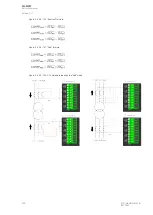
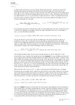
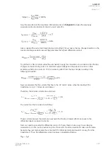
side current transformers are 1200/5 A. The primary side factor (p.u.) and current are then calculated
as follows:
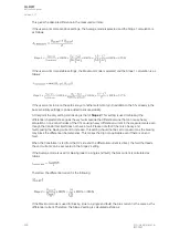
Then, the secondary side factor (p.u.) and current are calculated as follows:
A
AQ
Q-M257
-M257
Instruction manual
Version: 2.07
286
© Arcteq Relays Ltd
IM00021
Содержание AQ-M257
Страница 1: ...AQ M257 Motor protection IED Instruction manual...
Страница 2: ......
Страница 449: ...Figure 7 3 221 Example block scheme A AQ Q M257 M257 Instruction manual Version 2 07 Arcteq Relays Ltd IM00021 447...
Страница 470: ...Figure 8 14 243 Device installation A AQ Q M257 M257 Instruction manual Version 2 07 468 Arcteq Relays Ltd IM00021...

