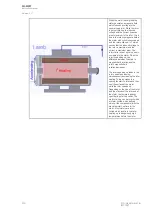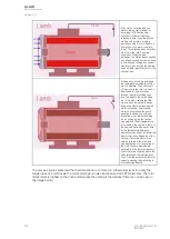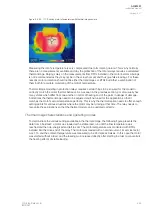
Figure. 5.4.23 - 117. Running motor's temperature with thermal image camera.
Measuring the rotor's temperature is very complicated due to its rotating nature. This is why normally
there are no measurements available and why the protection of the rotor always requires a calculated
thermal image. Relying solely on the measurements from RTDs installed in the motor's stator windings
is not recommended as they mey not be in the actual hot spot and thus give false readings. For these
reasons motor protection should not be either thermal images or RTDs but rather a combination of
them both for accurate monitoring of the motor's temperature.
Thermal image modeling in protection relays requires certain things to be ensured for the model to
correctly match the motor thermal behavior. As was seen in the previous section, a motor usually has
many states which differ from one another in terms of heating and of the parts in danger of damage.
Sometimes the thermal image needs to be adjusted and fine-tuned for the application so that it
matches the motor's actual temperature perfectly. This is why the thermal replica needs to offer enough
setting points for various situations where the motor may be running at that time. The relay needs to
recognize these situations so that the thermal model can be updated correctly.
Thermal image characteristics and operating modes
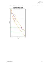
To demonstrate the various settings available in the thermal image, the following figure presents the
data from a field test: a motor was loaded with a stable load, run until the final temperature was
reached and then de-energized and left to cool. The motor temperature was monitored with RTDs
installed into the drive end of the relay. The motor was loaded with a nominal current, its service factor
was 1.15 and the ambient temperature was measured to be 24 degrees Celsius. In this case the motor
was started without a load, and the loading was increased directly after starting in order to concentrate
the heating effects of stable loading.
A
AQ
Q-M257
-M257
Instruction manual
Version: 2.07
© Arcteq Relays Ltd
IM00021
233
Содержание AQ-M257
Страница 1: ...AQ M257 Motor protection IED Instruction manual...
Страница 2: ......
Страница 449: ...Figure 7 3 221 Example block scheme A AQ Q M257 M257 Instruction manual Version 2 07 Arcteq Relays Ltd IM00021 447...
Страница 470: ...Figure 8 14 243 Device installation A AQ Q M257 M257 Instruction manual Version 2 07 468 Arcteq Relays Ltd IM00021...


