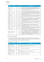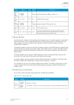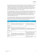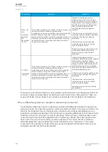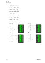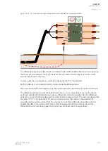
Figure. 5.4.29 - 156. Differential function characteristic, biased and non-biased.
The graph is the function of measured biasing current and the differential protection current. The red
line presents the allowed differential current in percentages. In this example the non-biased pick-up is
set lower than in a normal transformer application. The settings and the ranges of the differential
protection function are presented in the "Settings and signals" section of this topic.
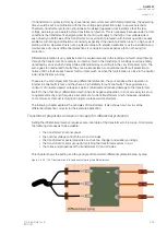
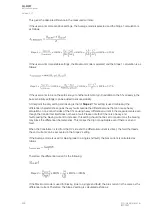
The biasing characteristic is formed with the following formulas:
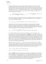
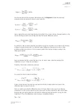
These form a straight line from zero current to Turnpoint (TP1). From TP1 to TP2 is the first slope
(Slope 1) which causes the set biasing to be coarser when the measured current amplitude increases.
When the measured current is higher that the TP2 set value, the second slope (Slope 2) is used.
Differential characteristics settings
Characteristics parts
One needs to understand what the various parts of the characteristics mean in order to set the
characteristics for the transformer application.
D
Diff
iff
bia
bias<TP1
s<TP1
= I
= I
d>pick-up
d>pick-up
This is the first straight line which represents the differential current created by the transformer's normal
operation. It takes into account measurement errors, possible variations caused by the transformer's
tap changer (if available), and the various reasons why the application might have caused a different
load inside the protected differential zone. In differential relays this is known as the pick-up current
(I
d>pick-up
). It is the basic sensitivity limit: when the measured differential current is below this limit, the
transformer still operates normally and the protection does not trigger. In other words, the pick-up
current setting must be higher than the combination of all the normal operation factors that cause
differential currents.
A
AQ
Q-M257
-M257
Instruction manual
Version: 2.07
292
© Arcteq Relays Ltd
IM00021
Содержание AQ-M257
Страница 1: ...AQ M257 Motor protection IED Instruction manual...
Страница 2: ......
Страница 449: ...Figure 7 3 221 Example block scheme A AQ Q M257 M257 Instruction manual Version 2 07 Arcteq Relays Ltd IM00021 447...
Страница 470: ...Figure 8 14 243 Device installation A AQ Q M257 M257 Instruction manual Version 2 07 468 Arcteq Relays Ltd IM00021...

