Connector
Description
Pin 1
mA OUT 1 + connector (0…24 mA)
Pin 2
mA OUT 1 – connector (0…24 mA)
Pin 3
mA OUT 2 + connector (0…24 mA)
Pin 4
mA OUT 2 – connector (0…24 mA)
Pin 5
mA OUT 3 + connector (0…24 mA)
Pin 6
mA OUT 3 – connector (0…24 mA)
Pin 7
mA OUT 4 + connector (0…24 mA)
Pin 8
mA OUT 4 – connector (0…24 mA)
Pin 9
mA IN 1 + connector (0…33 mA)
Pin 10
mA IN 1 – connector (0…33 mA)
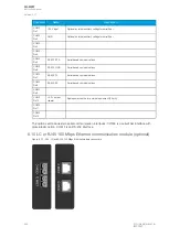
The milliampere (mA) I/O module is an add-on module with four (4) mA outputs and one (1) mA input.
Both the outputs and the input are in two galvanically isolated groups, with one pin for the positive (+)
connector and one pin for the negative (–) connector.
This module can be ordered directly to be installed into the device in the factory, or it can be upgraded
in the field after the device's original installation when required.
The user sets the mA I/O with the mA outputs control function. This can be done at
Control
→
Device
I/O
→
mA outputs in the relay configuration settings.
8.14 Dimensions and installation
The device can be installed either to a standard 19” rack or to a switchgear panel with cutouts. The
desired installation type is defined in the order code. When installing to a rack, the device takes a half
(½) of the rack's width, meaning that a total of two devices can be installed to the same rack next to
one another.
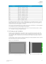
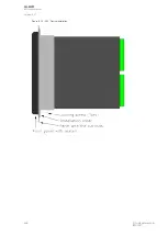
The figures below describe the device dimensions (first figure), the device installation (second), and the
panel cutout dimensions and device spacing (third).
Figure. 8.14 - 242. Device dimensions.
A
AQ
Q-M257
-M257
Instruction manual
Version: 2.07
© Arcteq Relays Ltd
IM00021
467
Содержание AQ-M257
Страница 1: ...AQ M257 Motor protection IED Instruction manual...
Страница 2: ......
Страница 449: ...Figure 7 3 221 Example block scheme A AQ Q M257 M257 Instruction manual Version 2 07 Arcteq Relays Ltd IM00021 447...
Страница 470: ...Figure 8 14 243 Device installation A AQ Q M257 M257 Instruction manual Version 2 07 468 Arcteq Relays Ltd IM00021...

