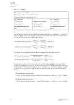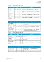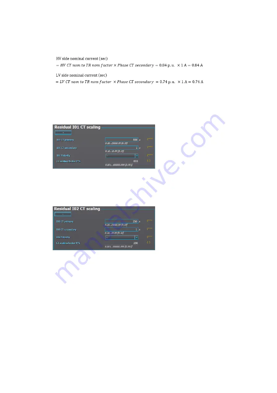
The secondary nominal current (in amperes) is the result of multiplying the per unit value with the
phase CT secondary side current. This current can be used when the unit is commissioned and when
the directions of CTs are checked. See the example calculation below:
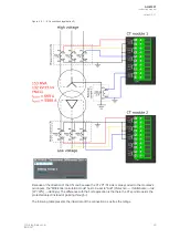
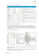
In case the phase current CTs are connected to the module via a Holmgren (summing) connection, the
use of coarse residual current measurement settings is required: the "I01 CT" settings are set
according to the phase current CTs' ratings (800/1 A).
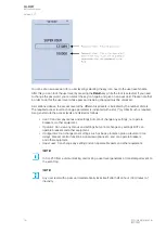
Figure. 5.2.1 - 6. Residual I01 CT scaling (coarse).
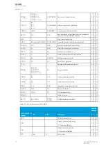
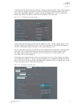
The residual current CT is connected to the first CTM directly, which requires the use of
sensitive residual current measurement settings: the "Residual I02 CT scaling" settings are set
according to the residual current CT's ratings (250/1 A).
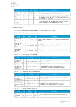
Figure. 5.2.1 - 7. Residual I02 CT scaling (sensitive).
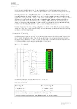
Example of CT scaling (application 2)
The following figure presents how the CTs are connected to the relay's measurement inputs. It also
shows the CT ratings and the transformer nominal current. Note that S1 is always connected to an odd
connector regardless of the CT direction. The CT direction is selected in the settings of the transformer
differential protection function.
A
AQ
Q-M257
-M257
Instruction manual
Version: 2.07
24
© Arcteq Relays Ltd
IM00021
Содержание AQ-M257
Страница 1: ...AQ M257 Motor protection IED Instruction manual...
Страница 2: ......
Страница 449: ...Figure 7 3 221 Example block scheme A AQ Q M257 M257 Instruction manual Version 2 07 Arcteq Relays Ltd IM00021 447...
Страница 470: ...Figure 8 14 243 Device installation A AQ Q M257 M257 Instruction manual Version 2 07 468 Arcteq Relays Ltd IM00021...


