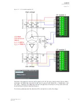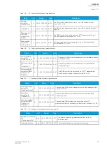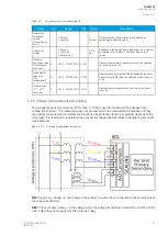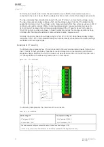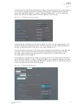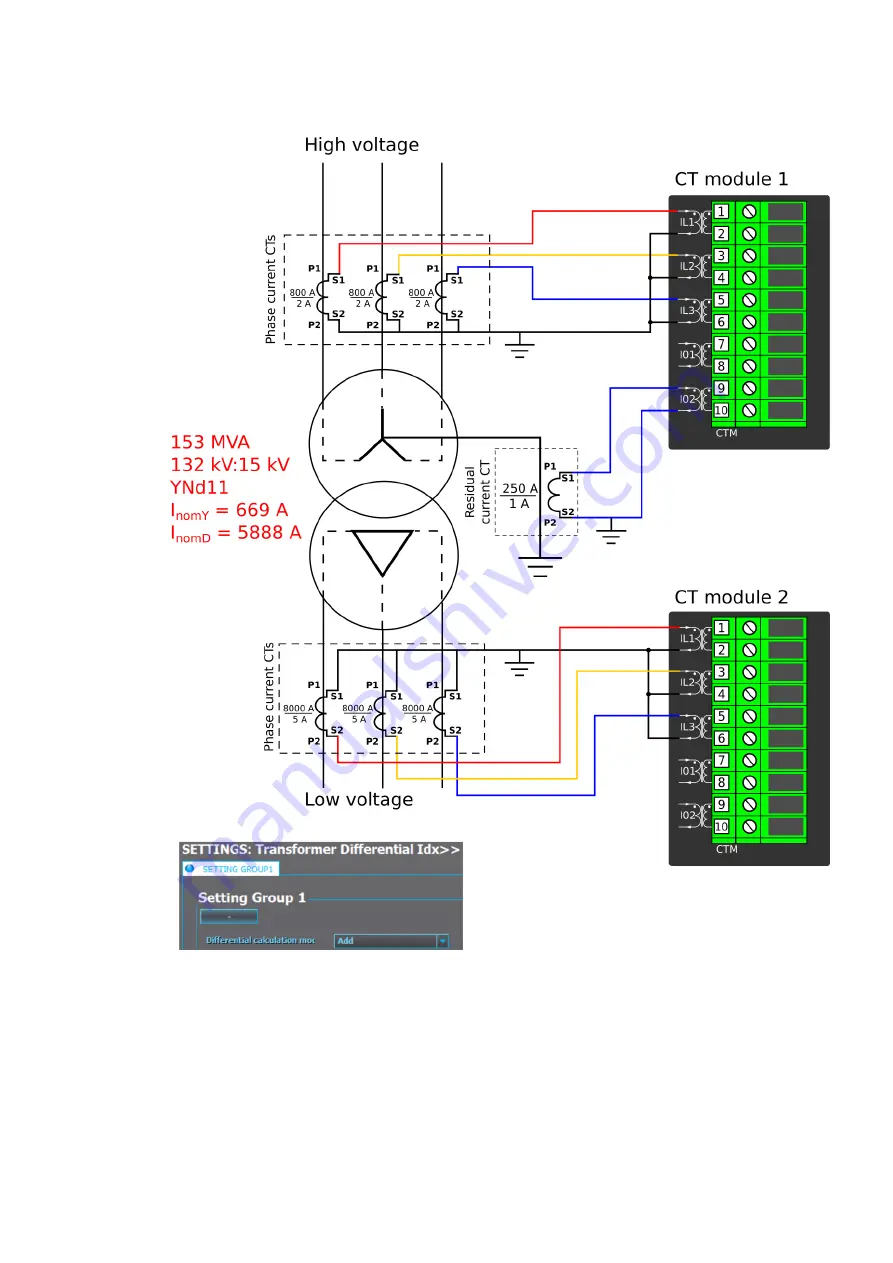
Figure. 5.2.1 - 8. Connections (application 2).
Because of the direction of the CTs and because the CTs' P1/S1 side is always wired to the modules's
odd inputs, the "Differential calculation mode" has to be set to "Add" (
Protection
→
TrafoModule
→
Idx>
[87T,87N]
→
Settings). The difference with the first application is that here the CTs point towards the
protected object instead of pointing through it.
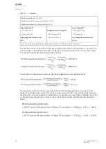
The following table presents the initial data of the connection as well as the ratings.
A
AQ
Q-M257
-M257
Instruction manual
Version: 2.07
© Arcteq Relays Ltd
IM00021
25
Содержание AQ-M257
Страница 1: ...AQ M257 Motor protection IED Instruction manual...
Страница 2: ......
Страница 449: ...Figure 7 3 221 Example block scheme A AQ Q M257 M257 Instruction manual Version 2 07 Arcteq Relays Ltd IM00021 447...
Страница 470: ...Figure 8 14 243 Device installation A AQ Q M257 M257 Instruction manual Version 2 07 468 Arcteq Relays Ltd IM00021...

