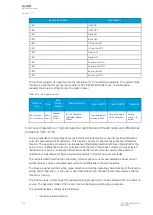
Name
Range
Step
Default
Description
Turnpoint
1
0.01…50.00×I
n
0.01×I
n
1.00×I
n
Setting for first turn point in the bias axe of the differential characteristics.
Slope 1
0.01…150.00% 0.01%
10.00%
Setting for the first slope of the differential characteristics.
Turnpoint
2
0.01…50.00×I
n
0.01×I
n
3.00×I
n
Setting for second turn point in the bias axe of the differential
characteristics.
Slope 2
0.01…250.00% 0.01%
40.00%
Setting for the second slope of the differential characteristics.
The pick-up settings can be selected via setting groups. The pick-up activation of the function is not
directly equal to the TRIP signal generation of the function. The TRIP signal is allowed if the blocking
condition is not active.
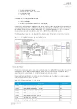
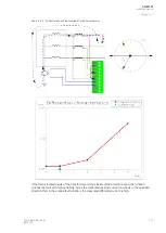
The following figure presents the differential characteristics with default settings.
Figure. 5.4.9 - 57. Differential characteristics for the I0d> function with default settings.
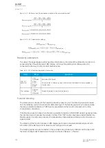
The equations for the differential characteristics are the following:
Figure. 5.4.9 - 58. Differential current (the calculation is based on user-selected inputs and direction).
A
AQ
Q-M257
-M257
Instruction manual
Version: 2.07
© Arcteq Relays Ltd
IM00021
127
Содержание AQ-M257
Страница 1: ...AQ M257 Motor protection IED Instruction manual...
Страница 2: ......
Страница 449: ...Figure 7 3 221 Example block scheme A AQ Q M257 M257 Instruction manual Version 2 07 Arcteq Relays Ltd IM00021 447...
Страница 470: ...Figure 8 14 243 Device installation A AQ Q M257 M257 Instruction manual Version 2 07 468 Arcteq Relays Ltd IM00021...

