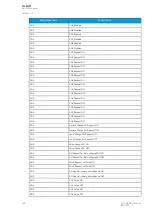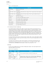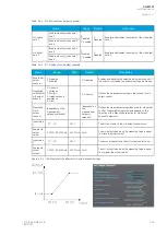
Table. 5.5.3 - 266. Register content.
Name
Description
Date and time
dd.mm.yyyy hh:mm:ss.mss
Event
Event name
Recorded Object opening
time
Time difference between the object receiving an "Open" command and the object receiving the
"Open" status.
Recorded Object closing
time
Time difference between the object receiving a "Close" command and object receiving the
"Closed" status.
Object status
The status of the object.
WD status
The status of the withdrawable circuit breaker.
Open fail
The cause of an "Open" command's failure.
Close fail
The cause of a "Close" command's failure.
Open command
The source of an "Open" command.
Close command
The source of an "Open" command.
General status
The general status of the function.
5.5.4 Indicator object monitoring
The indicator object monitoring function takes care of the status monitoring of disconnectors. The
function's sole purpose is indication and does not therefore have any control functionality. To control
circuit breakers and/or disconnectors, please use the Object control and monitoring function. The
monitoring is based on the statuses of the configured relay's digital inputs. The number of monitored
indicators in a relay depends on the device type and available inputs. The status monitoring of one
monitored object usually requires two (2) digital inputs. Alternatively, object status monitoring can be
performed with a single digital input: the input's active state and its zero state (switched to 1 with a
NOT gate in the Logic editor).
The outputs of the function are the monitored indicator statuses (Open, Close, Intermediate and Bad).
The setting parameters are static inputs for the function, which can only be changed by the use in the
function's setup phase.
The inputs of the function are the binary status indications. The function generates general time
stamped ON/OFF events to the common event buffer from each of the following signals: OPEN,
CLOSE, BAD and INTERMEDIATE event signals. The time stamp resolution is 1 ms.
Settings
Function uses available hardware and software digital signal statuses. These input signals are also
setting parameters for the function.
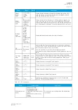
Table. 5.5.4 - 267. Indicator status.
Name
Range
Default
Description
Indicator
name
("Ind. Name")
-
IndX
The user-set name of the object, at maximum 32 characters long.
IndicatorX
Object status
("Ind.X Object
Status")
0:
Intermediate
1: Open
2: Closed
3: Bad
-
Displays the status of the indicator object. Intermediate status is displayed when
neither of the status conditions (open or close) are active. Bad status is displayed
when both of the status conditions (open and close) are active.
A
AQ
Q-M257
-M257
Instruction manual
Version: 2.07
356
© Arcteq Relays Ltd
IM00021
Содержание AQ-M257
Страница 1: ...AQ M257 Motor protection IED Instruction manual...
Страница 2: ......
Страница 449: ...Figure 7 3 221 Example block scheme A AQ Q M257 M257 Instruction manual Version 2 07 Arcteq Relays Ltd IM00021 447...
Страница 470: ...Figure 8 14 243 Device installation A AQ Q M257 M257 Instruction manual Version 2 07 468 Arcteq Relays Ltd IM00021...


