In modern relays these standard vector groups (Y or delta, lead or lag) are defined by a setting
selection and there is no need for interposing transformers. Even if the transformer's vector group is not
standard it should still be settable within the relay (such as with zigzag transformers).
In this example, the function translates the delta side currents. The correction applies not only to the
angles but also to the amplitudes because the delta side (in p.u.) is relative to the amplitude difference
with the Y-connected side.
This process is called vector group matching for the currents (in p.u.) of the transformer. This matching
is necessary whenever one side is connected to the delta and another to the Y. Previously in non-
numerical relays, this matching was done by interposing CTs which connected the power transformer's
Y side to the delta, and the transformer's delta side to the Y. This got the HV and LV side vectors to
match each other. Then the currents in the relay inputs are summed up. If there is no difference (as the
HV and LV side currents negate each other), the pick-up is not triggered. If the currents do
have a difference, the current flows to the relay input and with enough difference causes a pick-up and
a trip. However, as modern differential relays do this transformation by calculating the corrected vector
internally, this is also just nice-to-know information not related to the actual operation of the relay.
Figure. 5.4.29 - 149. Expected phase shifts from HV side to LV side (a symmetrical situation).
The direction of the CTs' Y legs on the HV and LV sides affects how the differential calculation method
is set. The setting options are "add" and "subtract" which is why the CTs' currenct direction has to be
taken into account. The "add" mode is used when the CT's starpoints are either pointing towards each
other or away from each other. The "subtract" mode is used when those points are pointing in the same
direction. In this example the correct setting would be the "add" mode because the CTs in the main
circuit are connected to the opposite and thus the measured currents from the CTs are also opposite.
The user selects how they want the signals shown: the CTs' currents can be negated with the "subtract"
option, resulting in a one Y-connected vector diagram.
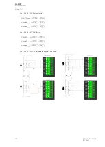
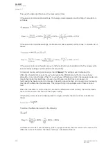
The images below present the differential algorithm itself (one calculating formula for each phase
difference); first the "subtract" formulas, then the "add" formulas. Selection is based on the CT
connections.
A
AQ
Q-M257
-M257
Instruction manual
Version: 2.07
© Arcteq Relays Ltd
IM00021
289
Содержание AQ-M257
Страница 1: ...AQ M257 Motor protection IED Instruction manual...
Страница 2: ......
Страница 449: ...Figure 7 3 221 Example block scheme A AQ Q M257 M257 Instruction manual Version 2 07 Arcteq Relays Ltd IM00021 447...
Страница 470: ...Figure 8 14 243 Device installation A AQ Q M257 M257 Instruction manual Version 2 07 468 Arcteq Relays Ltd IM00021...


