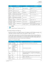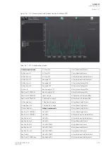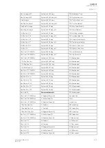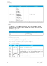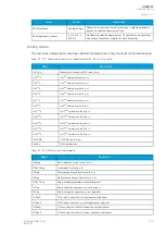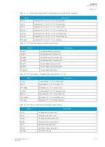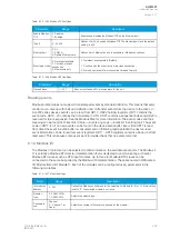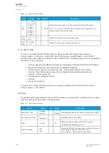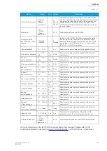
Table. 5.6.9 - 325. Event messages.
Event block name
Event name
RHC1
Running hour counter ON
RHC1
Running hour counter OFF
RHC1
Running hour counter cleared ON
RHC1
Running hour counter cleared OFF
5.7 Programmable stage (PGx>/<; 99)
The programmable stage is a stage that the user can program to create more advanced applications,
either as an individual stage or together with programmable logic. The relay has ten programmable
stages, and each can be set to follow one to three analog measurements. The programmable stages
have three available pick up terms options: overX, underX and rate-of-change of the selected signal.
Each stage includes a definite time delay to trip after a pick-up has been triggered.
The programmable stage cycle time is 5 ms. The pick-up delay depends on which analog signal is
used as well as its refresh rate (typically under a cycle in a 50 Hz system).
The number of programmable stages to be used is set in the
INFO tab. When this function has been
set as "Activated", the number of programmable stages can be set anywhere between one (1) and ten
(10) depending on how many the application needs. In the image below, the number of programmable
stages have been set to two which makes PS1 and PS2 to appear. Inactive stages are hidden until they
are activated.
Please note that setting the number of available stages does not activate those stages, as they also
need to be enabled individually with the
PSx >/< Enabled parameter. When enabled an active
stage shows its current state (condition), the expected operating time and the time remaining to trip
under the activation parameters. If a stage is not active the
PSx>/< condition parameter will merely
display “Disabled”.
The function's outputs are START, TRIP and BLOCKED signals. The programmable stage function
uses a total of eight (8) separate setting groups which can be selected from one common source.
The function can operate on instant or time-delayed mode. Definite time (DT) delay can be selected in
the In time-delayed mode.
The inputs for the function are the following:
• operating mode selections
• setting parameters
• digital inputs and logic signals
• measured and pre-processed magnitudes.
The function's outputs are START, TRIP and BLOCKED signals which can be used for direct I/O
controlling and user logic programming. The function generates general time-stamped ON/OFF events
to the common event buffer from each of the three (3) output signals. In the instant operating mode the
function outputs START and TRIP events simultaneously with an equivalent time stamp. The time stamp
resolution is 1 ms. The function also provides a resettable cumulative counter for the START, TRIP and
BLOCKED events.
General settings
The following general settings define the general behavior of the function. These settings are static i.e.
it is not possible to change them by editing the setting group.
A
AQ
Q-M257
-M257
Instruction manual
Version: 2.07
© Arcteq Relays Ltd
IM00021
413
Содержание AQ-M257
Страница 1: ...AQ M257 Motor protection IED Instruction manual...
Страница 2: ......
Страница 449: ...Figure 7 3 221 Example block scheme A AQ Q M257 M257 Instruction manual Version 2 07 Arcteq Relays Ltd IM00021 447...
Страница 470: ...Figure 8 14 243 Device installation A AQ Q M257 M257 Instruction manual Version 2 07 468 Arcteq Relays Ltd IM00021...

