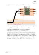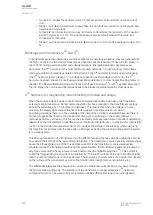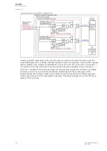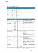
Figure. 5.4.29 - 169. System voltage and magnitude of the 5
th
harmonic component.
As can be seen in the figure above, the 5
th
harmonic component first increases, then decreases and
then increases again as the system voltage rises. In this case the 5
th
harmonic seems to disappear
completely when around an overvoltage of 160 %. When the harmonic behaves this way, the previously
mentioned blocking can be used as it automatically blocks on a smaller overvoltage (in case there is
any differential current) and releases when the overvoltage is too heavy and the differential current is
most probably over the tripping limit.
However, one should note that the behavior of this blocking is very unpredictable if the exact saturation
characteristic and the transformer design are not known. If there is a chance that the overexcitation
can cause problems (that is, no overvoltage relays are available), this blocking can be enabled with the
setting of 30...40 % with the disturbance recorder enabled. If a trip occurs as a result of overexcitation,
the settings can be adjusted based on the data captured by the disturbance recorder.
A
AQ
Q-M257
-M257
Instruction manual
Version: 2.07
314
© Arcteq Relays Ltd
IM00021
Содержание AQ-M257
Страница 1: ...AQ M257 Motor protection IED Instruction manual...
Страница 2: ......
Страница 449: ...Figure 7 3 221 Example block scheme A AQ Q M257 M257 Instruction manual Version 2 07 Arcteq Relays Ltd IM00021 447...
Страница 470: ...Figure 8 14 243 Device installation A AQ Q M257 M257 Instruction manual Version 2 07 468 Arcteq Relays Ltd IM00021...


