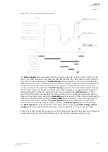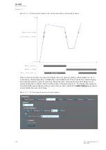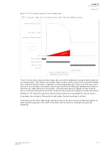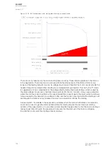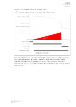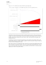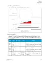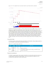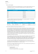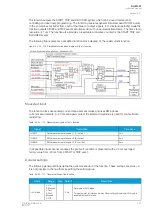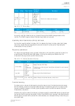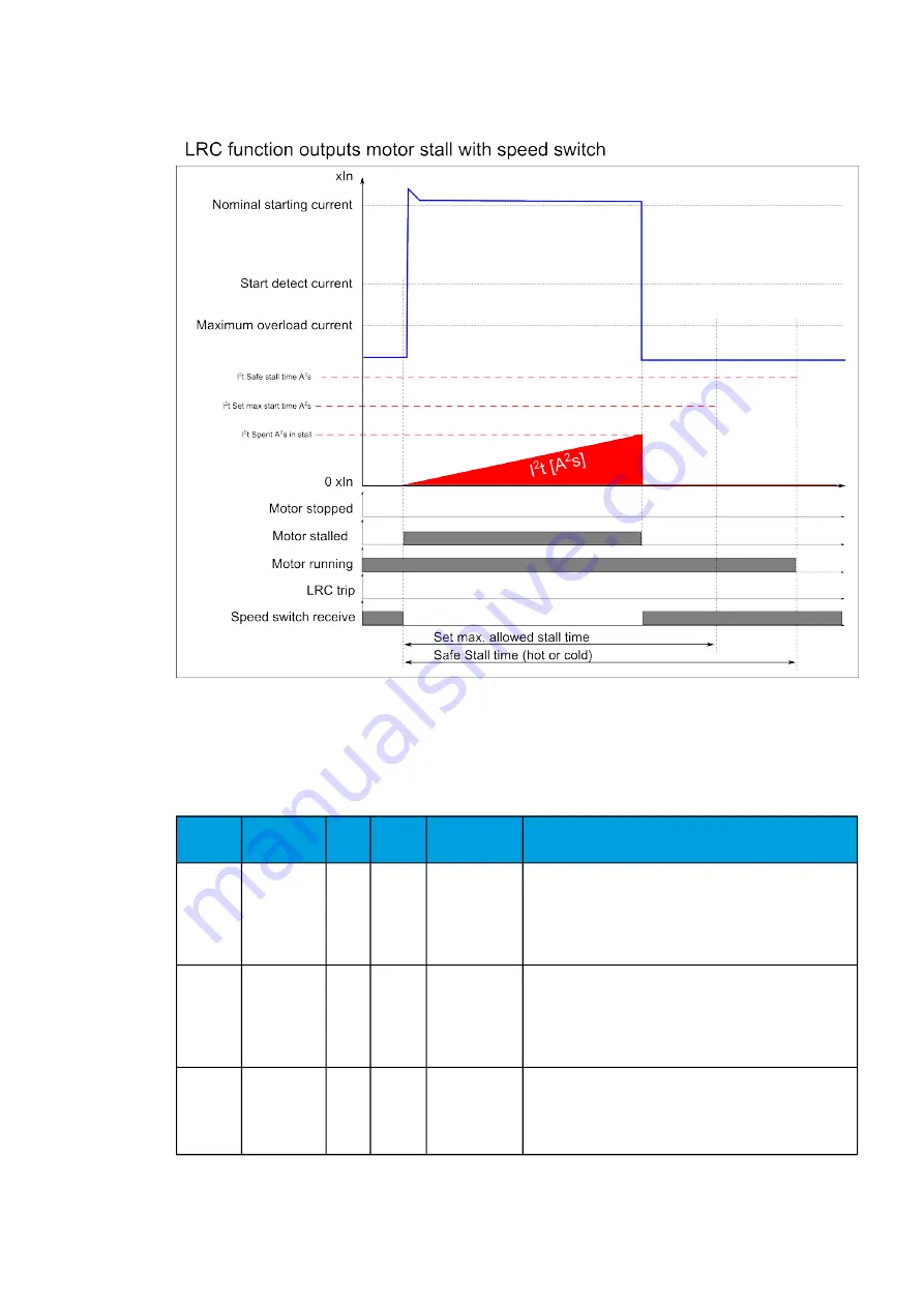
Figure. 5.4.18 - 102. Motor stall monitoring.
Settings and signals
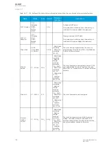
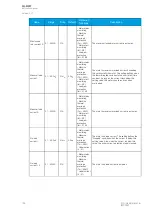
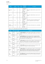
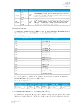
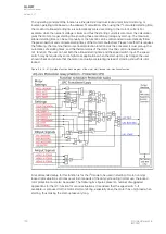
The settings of the motor start/locked rotor monitoring function are mostly shared with other motor
protection functions in the device's motor module. The following table shows the motor data settings of
the Ist> function.
Name
Range
Step Default
Protection
functions
Description
ISt> LN
mode
1: On
2: Blocked
3: Test
4: Test/
Blocked
5: Off
-
1: On
-
Set mode of LCR block.
This parameter is visible only when
Allow setting of individual
LN mode is enabled in General menu.
ISt> LN
behaviour
1: On
2: Blocked
3: Test
4: Test/
Blocked
5: Off
-
-
-
Displays the mode of LCR block.
This parameter is visible only when
Allow setting of individual
LN mode is enabled in General menu.
Motor
Start
0: DOL
1: Y-delta
2: Soft start
-
0: DOL
- Motor status
monitoring
- Motor start
monitoring
(Ist>; 48/14)
The motor starting mode selection. The user can select
between direct-on-line (DOL), Star-Delta and Soft start in
future releases.
A
AQ
Q-M257
-M257
Instruction manual
Version: 2.07
© Arcteq Relays Ltd
IM00021
195
Содержание AQ-M257
Страница 1: ...AQ M257 Motor protection IED Instruction manual...
Страница 2: ......
Страница 449: ...Figure 7 3 221 Example block scheme A AQ Q M257 M257 Instruction manual Version 2 07 Arcteq Relays Ltd IM00021 447...
Страница 470: ...Figure 8 14 243 Device installation A AQ Q M257 M257 Instruction manual Version 2 07 468 Arcteq Relays Ltd IM00021...

