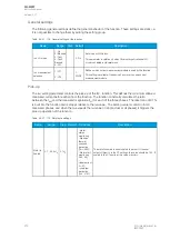
Events and registers
The frequent start protection function (abbreviated "FSP" in event block names) generates events from
the detected motor status. The data register is available, based on the changes in the events.
Table. 5.4.19 - 168. Event messages.
Event block name
Event names
FSP1
Alarm ON
FSP1
Alarm OFF
FSP1
Inhibit ON
FSP1
Inhibit OFF
FSP1
Blocked ON
FSP1
Blocked OFF
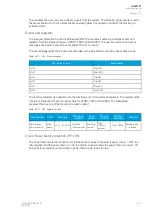
The function registers its operation into the last twelve (12) time-stamped registers. The table below
presents the structure of the function's register content.
Table. 5.4.19 - 169. Register content.
Date and time
Event
Inhibit time on
Time since last start
Start count
dd.mm.yyyy
hh:mm:ss.mss
Event
name
If on, it shows how long the
inhibit is active
Time elapsed from last
starting
Starts used at the triggering
moment
5.4.20 Non-directional undercurrent protection (I<; 37)
The non-directional undercurrent function is used for monitoring motor loading especially in conveyor-
type of applications. A sudden loss in the motor load indicates problems in the actual load rather than
in the motor itself. In a conveyor application this may indicate a broken belt and the motor should be
turned off immediately to avoid further problems. The cause may also be a mechanical breakdown of
the apparatus the motor uses. In some cases this undercurrent function's output may be also used in
an automation system to indicate that the device has finished its work load and is ready for a next task.
In order to operate this function requires
motor running status signal to be active. Motor running is
connected internally from
Motor status monitoring function. The operation of undercurrent protection is
blocked when the motor is not running.
The non-directional undercurrent function is used for instant and time-delayed undercurrent protection.
The operating decisions are based on phase current magnitude, constantly measured by the
function. The available phase current magnitudes are equal to RMS values. The blocking signal and the
setting group selection control the operating characteristics of the function during normal operation,
i.e. the user or user-defined logic can change function parameters while the function is running.
The function's outputs are START, TRIP and BLOCKED signals which can be used for direct I/O
controlling and user logic programming.. The undercurrent function uses a total of eight (8) separate
setting groups which can be selected from one common source.
The function can operate on instant or time-delayed mode. In the time-delayed mode the operation can
be set to operate on definite time (DT) delay.
The inputs for the function are the following:
• setting parameters
• digital inputs and logic signals
• measured and pre-processed current magnitudes.
A
AQ
Q-M257
-M257
Instruction manual
Version: 2.07
206
© Arcteq Relays Ltd
IM00021
Содержание AQ-M257
Страница 1: ...AQ M257 Motor protection IED Instruction manual...
Страница 2: ......
Страница 449: ...Figure 7 3 221 Example block scheme A AQ Q M257 M257 Instruction manual Version 2 07 Arcteq Relays Ltd IM00021 447...
Страница 470: ...Figure 8 14 243 Device installation A AQ Q M257 M257 Instruction manual Version 2 07 468 Arcteq Relays Ltd IM00021...

