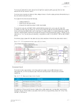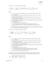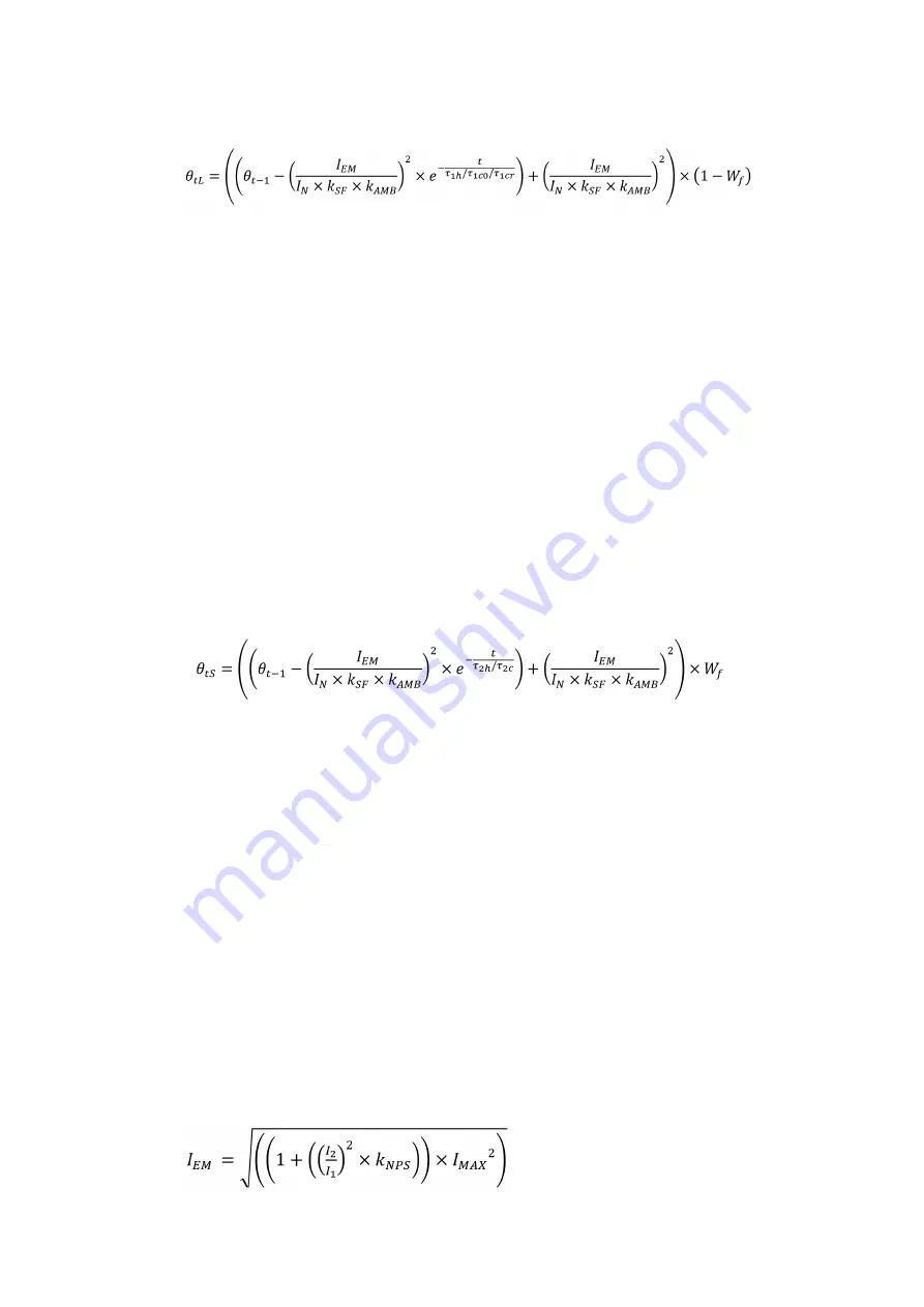
Figure. 5.4.23 - 110. Long time constant thermal image calculation.
Where:
• θ
t-1
= Thermal image status in a previous calculation cycle (the memory of the function)
• I
EM
= (see below)
• I
N
= Current for the 100 % thermal capacity to be used (pick-up current in p.u., with this
current t
max
achieved in time t)
• k
SF
= Loading factor (service factor) coefficient, the maximum allowed load current in p.u.,
depending on the protected object
• k
AMB
= Temperature correction factor, either from a linear approximation or from a settable
ten-point thermal capacity curve
• e = Euler's number
• t = Calculation time step in seconds (0.005 s)
• τ
1h
= Long thermal heating time constant of the protected object (in minutes)
• τ
1c0
= Long thermal cooling time constant (motor stopped) of the protected object (in
minutes)
• τ
1cr
= Long thermal cooling time constant (motor running) of the protected object (in minutes)
• W
f
= Correction factor between the times t
1
and t
2
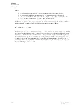
Figure. 5.4.23 - 111. Short time constant thermal image calculation.
Where:
• θ
t-1
= Thermal image status in a previous calculation cycle (the memory of the function)
• I
EM
= (see below)
• I
N
= Current for the 100 % thermal capacity to be used (pick-up current in p.u., with this
current t
max
achieved in time t)
• k
SF
= Loading factor (service factor) coefficient, the maximum allowed load current in
p.u. value, depending on the protected object
• k
AMB
= Temperature correction factor, either from a linear approximation or from a settable
ten-point thermal capacity curve
• e = Euler's number
• t = Calculation time step in seconds (0.005 s)
• τ
2h
= Short thermal heating time constant of the protected object (in minutes)
• τ
2c
= Short thermal cooling time constant of the protected object (in minutes)
• W
f
= Correction factor between the times t
1
and t
2
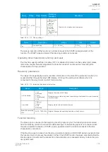
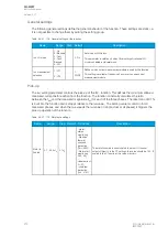
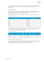
The equation below is that of the effective current of the protected object including the TRMS
measurement maximum phase current as well as a possible phase current unbalance condition.
A
AQ
Q-M257
-M257
Instruction manual
Version: 2.07
© Arcteq Relays Ltd
IM00021
223
Содержание AQ-M257
Страница 1: ...AQ M257 Motor protection IED Instruction manual...
Страница 2: ......
Страница 449: ...Figure 7 3 221 Example block scheme A AQ Q M257 M257 Instruction manual Version 2 07 Arcteq Relays Ltd IM00021 447...
Страница 470: ...Figure 8 14 243 Device installation A AQ Q M257 M257 Instruction manual Version 2 07 468 Arcteq Relays Ltd IM00021...

