Protective Elements
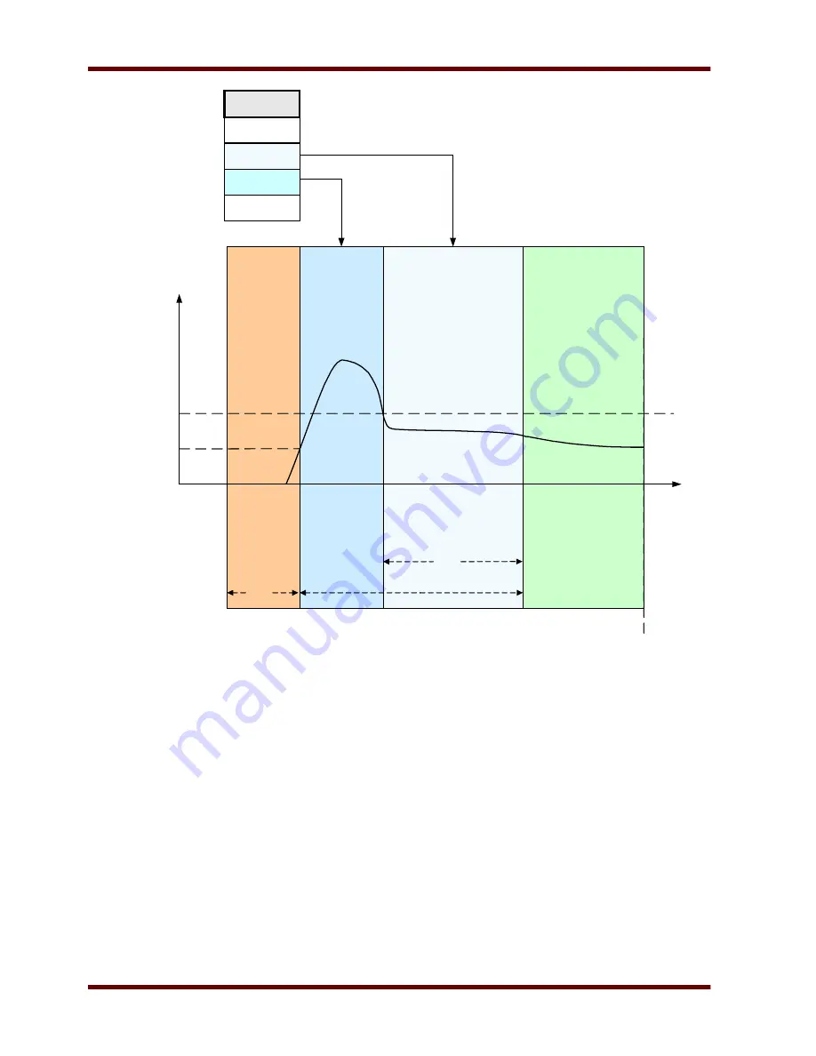
The Start Control Module drawing shows an example of how the protective device reacts to a normal operating-
cycle current profile. Initially, the motor is stopped and the current is zero. As long as the protective device is
not in a »trip« state, it permits contactor energization by closing its trip contact in series with the contactor. The
contactor is energized by the operator or process control system through a normal two-wire or three-wire motor
control scheme, external to the protective device. The protective device declares a motor start when it senses a
motor current that exceeds 30% of the »
Ib«
(FLA) setting. Meanwhile, the transition timer »
TRNT«
begins to
run. The protective device also monitors the large starting current, noting when the current falls below the
transition level »
TRNC«
.
Page 264
EN MRM4 01/11
Run
Start
Start
Stop
TRN I
t1
t2
t3
t4
t5
t6
Current
T1
T3
T1 : Stop Cycle
t4 – t3 : Start Cycle if TRNC is select
t6 – t3 : Start Cycle if TRNT is select
TRN TIME
TRN T or I
TRN T and I
TRN Criteria
I > 0,3 *Ib (FLA)
TRN I
t
T2=TRN TIME
Summary of Contents for MRM4
Page 1: ...MRM4 HighPROTEC Motor Protection Device Manual DOK HB MRM4E...
Page 3: ...Order Code EN MRM4 01 11 Page 3...
Page 18: ...Important Definitions Page 18 EN MRM4 01 11 41 SG Prot ON 42 SG ON Cmd SG Prot ON SG ON Cmd...
Page 115: ...Navigation Operation Navigation Operation EN MRM4 01 11 Page 115 1 2 3 5 7 6 8 10 9...
Page 162: ...Recorder Name Description I 2 TripCmd Signal Trip Command Page 162 EN MRM4 01 11...


