Fault Finding
DK424 RPSU280 Power Supply Test
14-6
Strata DK I&M 6/00
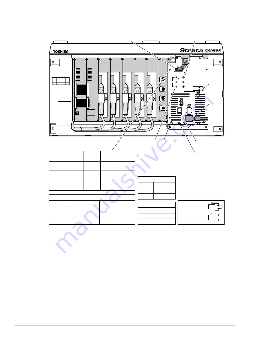
Figure 14-2
RPSU280 Power Supply Voltage Test Points / Circuit Breakers / Jumper Plugs
R11
PCTU
S11
S12
S13
S14
S15
S16
R11
S11
RCTU
S12
S13
S14
S15
S16
1
2
3
-24V
POWER
+5V
-5V
AC IN
FG
DC OUT
+
BATT
-
ON
OFF
DKSUE
DKSUB
4252
DC Out Cable/connector
FG Wire
and
Spade Lug
24VDC Circuit Breaker
Assignments:
Base
Jumper
Plug
AC
Power
Cord
ON/OFF Switch
DC VOLTAGE PINS
Power Indicator LEDs (Green)
–24VDC
Circuit
Breakers
Third Wire Ground or
Power Supply Daisy Chain
Ground to Next Power
Supply
DC VOLTAGE SPECIFICATION
–5VDC (+4.5 ~ +5.5)
–5VDC (–4.5 ~ –5.5),
Expansion Cabinet only
–24VDC (–26.3 ~ –27.8)
BATT (VDC)
+
–
0
–26.3 ~ –27.8*
24-1
24-2
24-3
SX1, SX2
SX3, SX4, SX5
SX6, SX7, SX8
EXP. CABINET
24V-1
24V-2
24V-3
S15, S16
S13, S14
S11, S12
BASE CABINET
Base
Jumper Plug
Expansion
Jumper Plug
Red
Wire
+5VDC
No
Wire
0VDC
Blue
Wire
–5VDC
White
Wire
+5VDC
Green
Wire
0VDC
Green
Wire
Green
Wire
0VDC
Yellow
Wire
–24VDC
Yellow
Wire
–24VDC
Yellow
Wire
–24VDC
0VDC
*RPSU424 “BATT” is 0 volt unless connected to good batteries.
Summary of Contents for Strata AirLink DK40i
Page 22: ...Introduction Related Documents Media xx Strata DK I M 6 00 ...
Page 48: ...DK14 Installation DK14 Wiring Diagrams 1 26 Strata DK I M 6 00 ...
Page 220: ...DK424 Installation Remote Cabinet Installation Instructions 5 68 Strata DK I M 6 00 ...
Page 262: ...DK424i Configuration Primary Reserve Power Cabinet Hardware 6 42 Strata DK I M 6 00 ...
Page 450: ...Universal Slot PCB Wiring Option Interface PCB Wiring Diagrams 10 42 Strata DK I M 6 00 ...
Page 592: ...Peripheral Installation Enhanced 911 Service E911 12 84 Strata DK I M 6 00 ...
Page 616: ...ACD Installation Spectrum Electronic Wall Boards 13 24 Strata DK I M 6 00 ...
Page 634: ...Fault Finding Fault Isolation Flowcharts 14 18 Strata DK I M 6 00 ...
Page 704: ...ISDN Interfaces ISDN Disconnect Cause Code 16 54 Strata DK I M 6 00 ...


