DK424 Installation
Printed Circuit Board (PCB) Installation
Strata DK I&M 6/00
5-45
DK424 Installa
tion
Printed Circuit Board (PCB) Installation
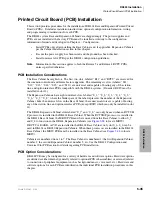
This section provides procedures for the installation of DK424 Base and Expansion Printed Circuit
Boards (PCBs). It includes installation instructions, optional configuration information, wiring,
and programming considerations for each PCB.
The DK424 system Base and Expansion Cabinets are shipped empty. The power supplies and
PCBs are not installed at the factory. PCBs must be installed according to the configuration
information obtained and developed in Chapter 4 – Configuration.
●
Install PCBs only after installing the Base Cabinet and, if applicable, Expansion Cabinets
per the Cabinet Installation section in this chapter.
●
Be sure the power supply has been tested and the ground has been checked.
●
Install universal slot PCBs per the DK424 configuration guidelines.
Note
Information in this section applies to both the Release 3 and Release 4 RCTU PCBs,
unless specified otherwise.
PCB Installation Considerations
The Base Cabinet has eight slots. The first two slots, labeled “R11” and “RCTU” are reserved for
the common control unit and future feature upgrades. The remaining six slots (labeled “S11,”
“S12,” “S13,” “S14,” “S15,” and “S16”) are universal and capable of hosting any of the station,
line, and option interface PCBs compatible with the DK424 systems. (If needed, RSIU must be
installed in slot 11.)
The Expansion Cabinets have eight universal slots, labeled “S_1,” “S_2,” S_3,” “S_4,” “S_5,”
“S_6,” “S_7,”“S_8,” where the blank space of the label represents the number of the Expansion
Cabinet. Like the universal slots in the Base Cabinet, these universal slots are capable of hosting
any of the station, line, and option interface PCBs (except RSIU which can only be installed in slot
11).
The DK424 Expansion Cabinet slots labeled “S_7” and “S_8,” can only be used when an RCTUE/
F processor is installed in the DK424 Base Cabinet. When the RCTUE/F processor is installed in
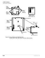
the DK424 Base Cabinet, the MBJU PCB must be removed from the Base Cabinet to allow S_7
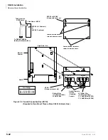
and S_8 to function in the DK424 Expansion Cabinets (see
to locate MBJU).
If RCTUA, BA/BB, or C/D are installed in the DK424 Base Cabinet, only slot S_1~S_6 can be
used in DK424 or DK280 Expansion Cabinets. When these processors are installed in the DK424
Base Cabinet, the MBJU PCB must be installed on the Base Cabinet (see
to locate
MBJU).
Cabinets are numbered from 1 to 7. The Base Cabinet is numbered 1; the first Expansion Cabinet,
number 2; the second Expansion Cabinet, number 3; etc. See the DK424 Configuration and
Universal Slot PCB section for details regarding PCB installation.
PCB Option Considerations
DK424 PCBs may be configured for a variety of hardware and software options. Hardware options
are defined as either internal (generally related to optional PCB subassemblies) or external (related
to connection of peripheral equipment such as background music, voice mail, etc.). Hardware and
software options for each PCB are identified in the individual PCB installation procedures in this
chapter.
Summary of Contents for Strata AirLink DK40i
Page 22: ...Introduction Related Documents Media xx Strata DK I M 6 00 ...
Page 48: ...DK14 Installation DK14 Wiring Diagrams 1 26 Strata DK I M 6 00 ...
Page 220: ...DK424 Installation Remote Cabinet Installation Instructions 5 68 Strata DK I M 6 00 ...
Page 262: ...DK424i Configuration Primary Reserve Power Cabinet Hardware 6 42 Strata DK I M 6 00 ...
Page 450: ...Universal Slot PCB Wiring Option Interface PCB Wiring Diagrams 10 42 Strata DK I M 6 00 ...
Page 592: ...Peripheral Installation Enhanced 911 Service E911 12 84 Strata DK I M 6 00 ...
Page 616: ...ACD Installation Spectrum Electronic Wall Boards 13 24 Strata DK I M 6 00 ...
Page 634: ...Fault Finding Fault Isolation Flowcharts 14 18 Strata DK I M 6 00 ...
Page 704: ...ISDN Interfaces ISDN Disconnect Cause Code 16 54 Strata DK I M 6 00 ...


