DK40i Installation
Power Supply Removal and Replacement
Strata DK I&M 6/00
3-19
D
K
40
i Installation
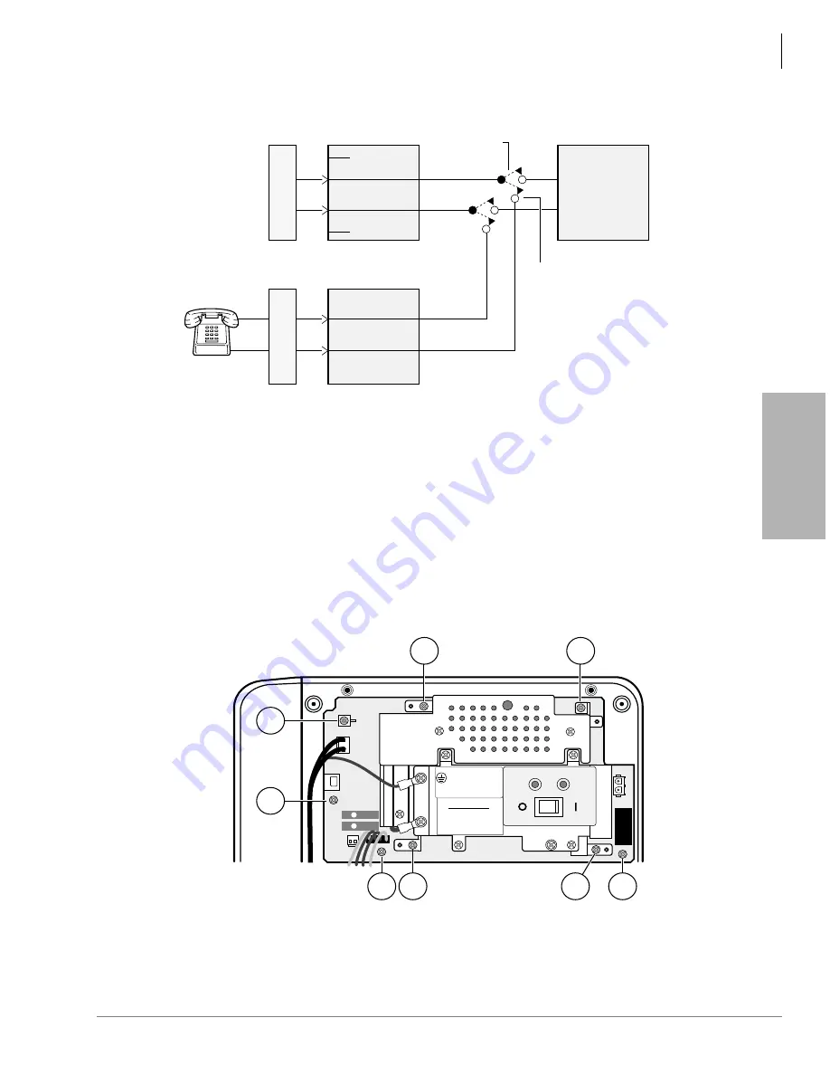
Figure 3-13 Base KSU Power Failure Transfer (PFT) Circuit Diagram
Power Supply Removal and Replacement
The power supply (TPSU16A) comes factory-installed in the Base KSU; if necessary, it can be
removed and replaced.
Power Supply Removal
1. Make sure that the power supply switch is Off and that the AC power cable is not plugged into
an outlet. Confirm that the green AC LED is not lit (see
Figure 3-14 Power Supply (TPSU16A)
4
3
5
2
MOD Jack CO1
(Base KSU)
MDF
TCOU
CO
Line
MOD Jack PF1
(Base KSU)
R
T
MDF
PFT
Standard
Telephone
T
R
Power Fail
Connection
Power Available
Connection
TCOU
CO Line 1
2155
FG2
POWER SUPPLY ASSEMBLY
MODEL
INPUT: AC127V 2.2A 60 HZ
OUTPUT: -27.3V 2.8A. -27.3V 0.2A
V. 1A 1996-05 00001
TOSHIBA CORPORATION
TPSU16A
MADE IN
WARNING
Hazardous voltage inside!
If servicing required
remove A. C. plug.
12
+
-
BATT
PN2
FG4
12
AC
DC
DC POWER
FG
FG1
-24V
-24V
1643
1
2
3
4
5
6
7
8
Summary of Contents for Strata AirLink DK40i
Page 22: ...Introduction Related Documents Media xx Strata DK I M 6 00 ...
Page 48: ...DK14 Installation DK14 Wiring Diagrams 1 26 Strata DK I M 6 00 ...
Page 220: ...DK424 Installation Remote Cabinet Installation Instructions 5 68 Strata DK I M 6 00 ...
Page 262: ...DK424i Configuration Primary Reserve Power Cabinet Hardware 6 42 Strata DK I M 6 00 ...
Page 450: ...Universal Slot PCB Wiring Option Interface PCB Wiring Diagrams 10 42 Strata DK I M 6 00 ...
Page 592: ...Peripheral Installation Enhanced 911 Service E911 12 84 Strata DK I M 6 00 ...
Page 616: ...ACD Installation Spectrum Electronic Wall Boards 13 24 Strata DK I M 6 00 ...
Page 634: ...Fault Finding Fault Isolation Flowcharts 14 18 Strata DK I M 6 00 ...
Page 704: ...ISDN Interfaces ISDN Disconnect Cause Code 16 54 Strata DK I M 6 00 ...


