Peripheral Installation
Power Failure Options
12-2
Strata DK I&M 6/00
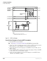
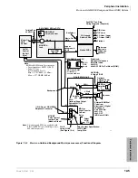
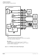
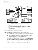
Figure 12-1
DPFT Circuit Diagram
Power Failure Emergency Transfer (DPFT) Installation
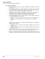
1. Mount the DPFT on or near the MDF.
Note
See
Chapter 10 – Universal Slot PCB Wiring
, DPFT/MDF interconnecting tables.
2. Using 25-pair cables with amphenol-type connectors (female for DPFT connector J1, male for
DPFT connector J2), connect the DPFT to two 66-type quick-connect blocks.
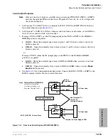
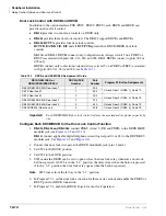
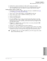
3. Connect the CO lines selected for emergency use to the DPFT J1-block “CO-TIP” and “CO-
RING” terminals.
4. Connect the RCOU, RCOS (or PCOU) circuits related to the emergency CO lines to the DPFT
J1-block “RCOU-TIP” and “RCOU-RING” terminals.
5. Connect the standard telephone stations selected for emergency use to the DPFT J2-block
“TEL-TIP” and “TEL-RING” terminals.
J2-26
J2-1
J1-26
J1-1
Relay
J1-25
J1-50
J1-2
J1-27
J2-2
J2-27
Telephone Current
Detector
To TEL-T1
To TEL-R1
To CO-T1
To CO-R1
To RSTU/PSTU-T1
RDSU/RSTS
To RSTU/PSTU-R1
RDSU/RSTS
To RCOU/PCOU-T1
To RCOU/PCOU-R1
DG (Input)
-24V (Input)
RSTU or PSTU
Control
1498
Notes
•
Representation of first of eight circuits.
•
Conditions shown with AC power (-24VDC) off.
Summary of Contents for Strata AirLink DK40i
Page 22: ...Introduction Related Documents Media xx Strata DK I M 6 00 ...
Page 48: ...DK14 Installation DK14 Wiring Diagrams 1 26 Strata DK I M 6 00 ...
Page 220: ...DK424 Installation Remote Cabinet Installation Instructions 5 68 Strata DK I M 6 00 ...
Page 262: ...DK424i Configuration Primary Reserve Power Cabinet Hardware 6 42 Strata DK I M 6 00 ...
Page 450: ...Universal Slot PCB Wiring Option Interface PCB Wiring Diagrams 10 42 Strata DK I M 6 00 ...
Page 592: ...Peripheral Installation Enhanced 911 Service E911 12 84 Strata DK I M 6 00 ...
Page 616: ...ACD Installation Spectrum Electronic Wall Boards 13 24 Strata DK I M 6 00 ...
Page 634: ...Fault Finding Fault Isolation Flowcharts 14 18 Strata DK I M 6 00 ...
Page 704: ...ISDN Interfaces ISDN Disconnect Cause Code 16 54 Strata DK I M 6 00 ...

