ISDN Interfaces
RBSU/RBSS and TBSU Interface Units
Strata DK I&M 6/00
16-27
ISDN
Inte
rface
s
The TBSU and RBSU/RBSS BRI-NT circuit supports the National ISDN 2 (NI2) S-Interface
“passive bus.” It is called a passive bus, because it contains no logical functions. The TBSU and
RBSU/RBSS BRI-NT interface supports a point-to-multipoint connection on two twisted pairs.
Up to two TE-1 and/or TA devices can be connected to one TBSU or RBSU/RBSS, BRI-NT
circuit. Using standardized wiring and modular connectors, as explained in previous paragraphs,
maintains control of polarity. The pinout from the TBSU and RBSU/RBSS circuit to a S-type TE-
1 or TA device is shown in
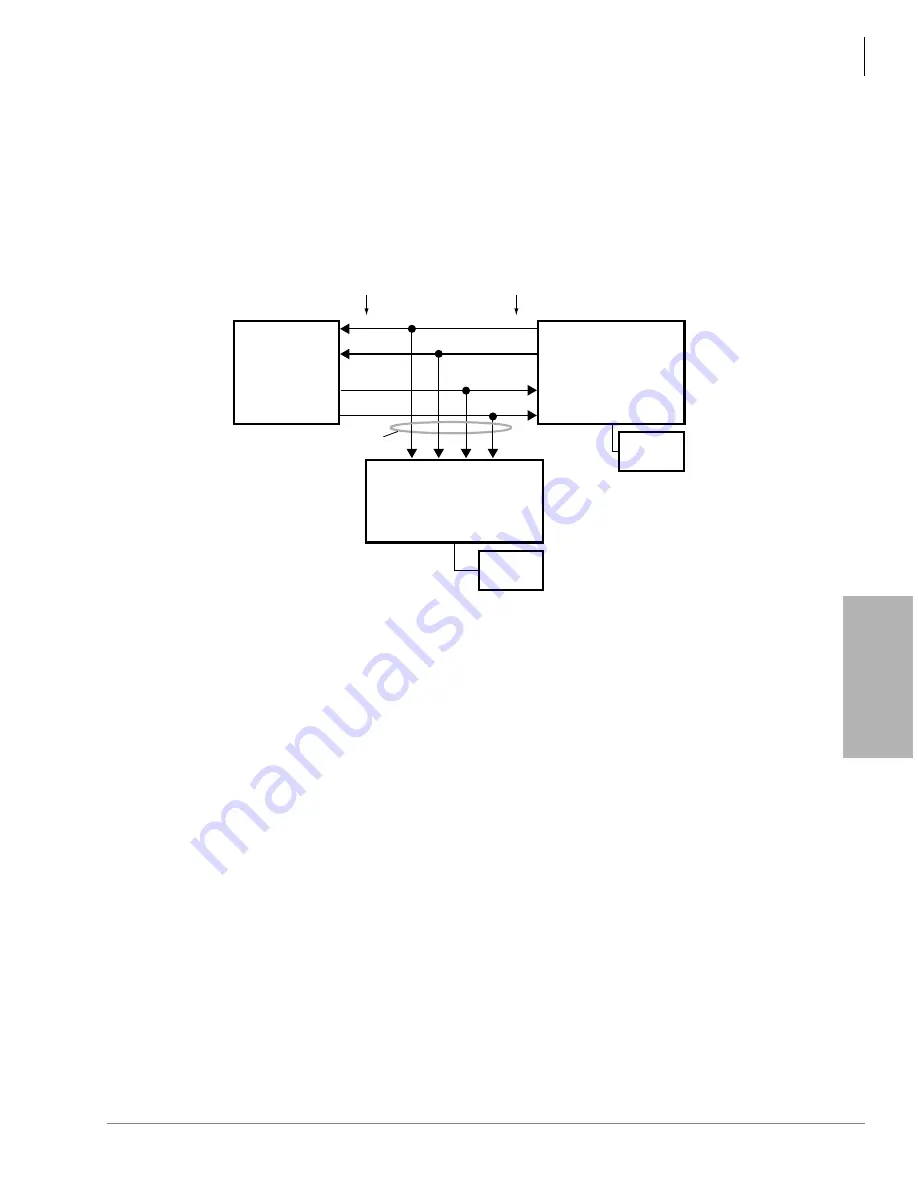
Figure 16-18 TBSU and RBSU/RBSS NT Circuit Pinout on Passive Bus
As a parallel bus, the TBSU and RBSU/RBSS BRI-NT passive bus will accept TE-1 and TA
devices scattered on the bus; however, the locations of the TE and TA devices on the S bus is
limited by timing considerations. Specifically, the round trip propagation delay of a signal from the
TBSU or RBSU/RBSS circuit to one device must be within four microseconds of the delay from
the other device on the bus. That is to say, layer-1 frames from the TBSU and RBSU/RBSS must
be received within a two microsecond window. This says nothing about how large the delay can
be. In fact, it can be much larger, as long as the differences remain small.
To control electrical characteristics, a 100-ohm terminating resistor (TR) is required at both ends
of the passive bus. One resistor should be across the Tx pair and one across the Rx pair at either
end of the passive bus. Branch-type passive bus configurations, shown in
,
may only require a TR on the TBSU or RBSU/RBSS NT circuit side and not on the TE or TA
device side of the bus.
The TBSU, RBSU, and RBSS circuits provide an option switch that allows the 100-ohm TR to be
switched into the circuit on the DK side of the bus (see
). Most TE-1 and TA devices also provide option switches to connect 100-ohm
terminating resistors as shown in
.
If the TE or TA devices do not provide TRs, they may be permanently wired in place on a RJ45
jack at the far end of the bus. Only one terminating resistor on each pair should be on the far (TE)
end of the passive bus - do not switch in TRs on more than one TE-1 or TA device on the passive
bus.
TBSU or RBSU
NT Circuit
Insert 100-ohm
TR using RBSU
and RBSS
option switches.
RJ45
Pinout
3344
S-type, TE-1s or TAs without
100-ohm terminating resistors
(maximum eight TE-1s or TAs per
RBSU/RBSS circuit).
BRI (four-wire)
3
6
4
5
3
6
4
5
RJ45
Pinout
S-type, TE-1 or TA with
100-ohm TR or just a
100-ohm terminating
resistor across each pair
on a RJ-45 jack.
To local
AC Power
To local
AC Power
3
6
4
5
Summary of Contents for Strata AirLink DK40i
Page 22: ...Introduction Related Documents Media xx Strata DK I M 6 00 ...
Page 48: ...DK14 Installation DK14 Wiring Diagrams 1 26 Strata DK I M 6 00 ...
Page 220: ...DK424 Installation Remote Cabinet Installation Instructions 5 68 Strata DK I M 6 00 ...
Page 262: ...DK424i Configuration Primary Reserve Power Cabinet Hardware 6 42 Strata DK I M 6 00 ...
Page 450: ...Universal Slot PCB Wiring Option Interface PCB Wiring Diagrams 10 42 Strata DK I M 6 00 ...
Page 592: ...Peripheral Installation Enhanced 911 Service E911 12 84 Strata DK I M 6 00 ...
Page 616: ...ACD Installation Spectrum Electronic Wall Boards 13 24 Strata DK I M 6 00 ...
Page 634: ...Fault Finding Fault Isolation Flowcharts 14 18 Strata DK I M 6 00 ...
Page 704: ...ISDN Interfaces ISDN Disconnect Cause Code 16 54 Strata DK I M 6 00 ...


