Universal Slot PCBs
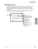
PCB Chapter Layout
9-6
Strata DK I&M 6/00
Table 9-1
BVPU Controls, Indicators, and Connectors
Control/Indicator/
Connector
Type of Component
Description
Serial Port
RS-232C Maintenance Connection
LAN Connector
RJ45
10BaseT Ethernet Connection
SW0
Dipswitch
Unused. All switches = Off
LED 1
Green LED
On = Tie trunk 4 active
LED 2
Green LED
On = Tie trunk 3 active
LED 3
Green LED
On = Tie trunk 2 active
LED 4
Green LED
On = Tie trunk 1 active
LED 5
Green LED
Power On/Off
LED 6
Yellow LED
Line Status (On=Busy / Off = Idle)
LED 7
Red LED
Alarm (On = Abnormal)
LED 8
Green LED
On-Line
On = Operating
Off = Starting up or Off
Slow Flash = Detected error in BVPU
Fast Flash = Shut down mode
LED 9
Yellow LED
Link Indication (On = Normal)
LED 10
Green LED
Data (On = Data communication in progress)
LED 11
Yellow LED
Collision (On = collisions occurring)
Summary of Contents for Strata AirLink DK40i
Page 22: ...Introduction Related Documents Media xx Strata DK I M 6 00 ...
Page 48: ...DK14 Installation DK14 Wiring Diagrams 1 26 Strata DK I M 6 00 ...
Page 220: ...DK424 Installation Remote Cabinet Installation Instructions 5 68 Strata DK I M 6 00 ...
Page 262: ...DK424i Configuration Primary Reserve Power Cabinet Hardware 6 42 Strata DK I M 6 00 ...
Page 450: ...Universal Slot PCB Wiring Option Interface PCB Wiring Diagrams 10 42 Strata DK I M 6 00 ...
Page 592: ...Peripheral Installation Enhanced 911 Service E911 12 84 Strata DK I M 6 00 ...
Page 616: ...ACD Installation Spectrum Electronic Wall Boards 13 24 Strata DK I M 6 00 ...
Page 634: ...Fault Finding Fault Isolation Flowcharts 14 18 Strata DK I M 6 00 ...
Page 704: ...ISDN Interfaces ISDN Disconnect Cause Code 16 54 Strata DK I M 6 00 ...

