ISDN Interfaces
ISDN Testing and Troubleshooting
16-36
Strata DK I&M 6/00
Notes
●
PS2 and PS3 are not used with the DK BRI-U interface PCBs.
●
Check with the BRI circuit supplier to determine the pin out of the demarc jacks because some
jacks may be wired with two or three BRI-U line circuits each jack.
Station-Side cabling
♦
The ISDN BRI U-interface circuits are two-wire on the DK station-side.
♦
The maximum distance between the DK ISDN BRI-U, station-side circuit (LT) and the U-type
Terminal Equipment or Terminal Adapter is 18kft.
♦
The house wiring from the DK BRI circuit to the wall jack should be made with CAT3~ CAT5
twisted pair wire.
♦
Each station-side BRI circuit requires a ferrite core as shown in
.
♦
The flat satin telephone cord that connects from the wall jacks to ISDN terminal equipment
should be no longer than 33 feet.
♦
BRI station-side cables should not be shielded.
♦
Polarity of the U interface pair is not critical.
♦
The U interface pair should go directly from the DK interface PCB to the U-type TE1 or TA
with no bridge taps or loading coils to different locations.
♦
The pin-out of the TBUU and RBUU/RBSU BRI jack is shown in
Call Monitor Jack Cabling
The pin-out for the BRI-U interface call monitor jack is provided in
of this chapter.
ISDN Testing and Troubleshooting
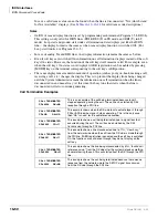
BRI-U, LT Interface Terminal Loop Back Test
The DK provides a built-in loop back test to check the U-type, lSDN terminal connected to the
RBUU, RBUS, or TBUU circuit. The DK performs the 2B+D loop test using the eoc ISDN, layer
1 function. This tests the U-terminal and the wire connection from the DK to the BRI device; it
does not check the DK PCM highway or RBUU/RBUS/TBUU functionality.
1. Set DK BRI programs to enable the BRI circuit to function. Make sure to setup the BRI circuit
in the station-side, LT mode using Program *60.
2. Connect the U-terminal device to the DK BRI, RJ45 circuit jack. (see
3. Connect the DK TTY port (PIOU, RSIU, TSIU, etc.) to the COM port of a PC running a
communications application such as ProComm or Hyper Terminal, etc.
Summary of Contents for Strata AirLink DK40i
Page 22: ...Introduction Related Documents Media xx Strata DK I M 6 00 ...
Page 48: ...DK14 Installation DK14 Wiring Diagrams 1 26 Strata DK I M 6 00 ...
Page 220: ...DK424 Installation Remote Cabinet Installation Instructions 5 68 Strata DK I M 6 00 ...
Page 262: ...DK424i Configuration Primary Reserve Power Cabinet Hardware 6 42 Strata DK I M 6 00 ...
Page 450: ...Universal Slot PCB Wiring Option Interface PCB Wiring Diagrams 10 42 Strata DK I M 6 00 ...
Page 592: ...Peripheral Installation Enhanced 911 Service E911 12 84 Strata DK I M 6 00 ...
Page 616: ...ACD Installation Spectrum Electronic Wall Boards 13 24 Strata DK I M 6 00 ...
Page 634: ...Fault Finding Fault Isolation Flowcharts 14 18 Strata DK I M 6 00 ...
Page 704: ...ISDN Interfaces ISDN Disconnect Cause Code 16 54 Strata DK I M 6 00 ...


