DK14 Installation
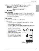
QCDU2 - CO Line Digital Telephone Interface Unit
Strata DK I&M 6/00
1-13
DK14 Installa
ti
on
QCDU2 - CO Line Digital Telephone Interface Unit
Circuits per PCB:
one loop start CO line circuit and two digital telephone circuits
Interfaces with:
digital telephones
PDIU-DIs/PDIU-DI2s/RPCI-DI
ADMs connected to the telephones and PDIU-DSs
Does not support a DDSS console or DDCB
Older Version(s):
QCDU1A
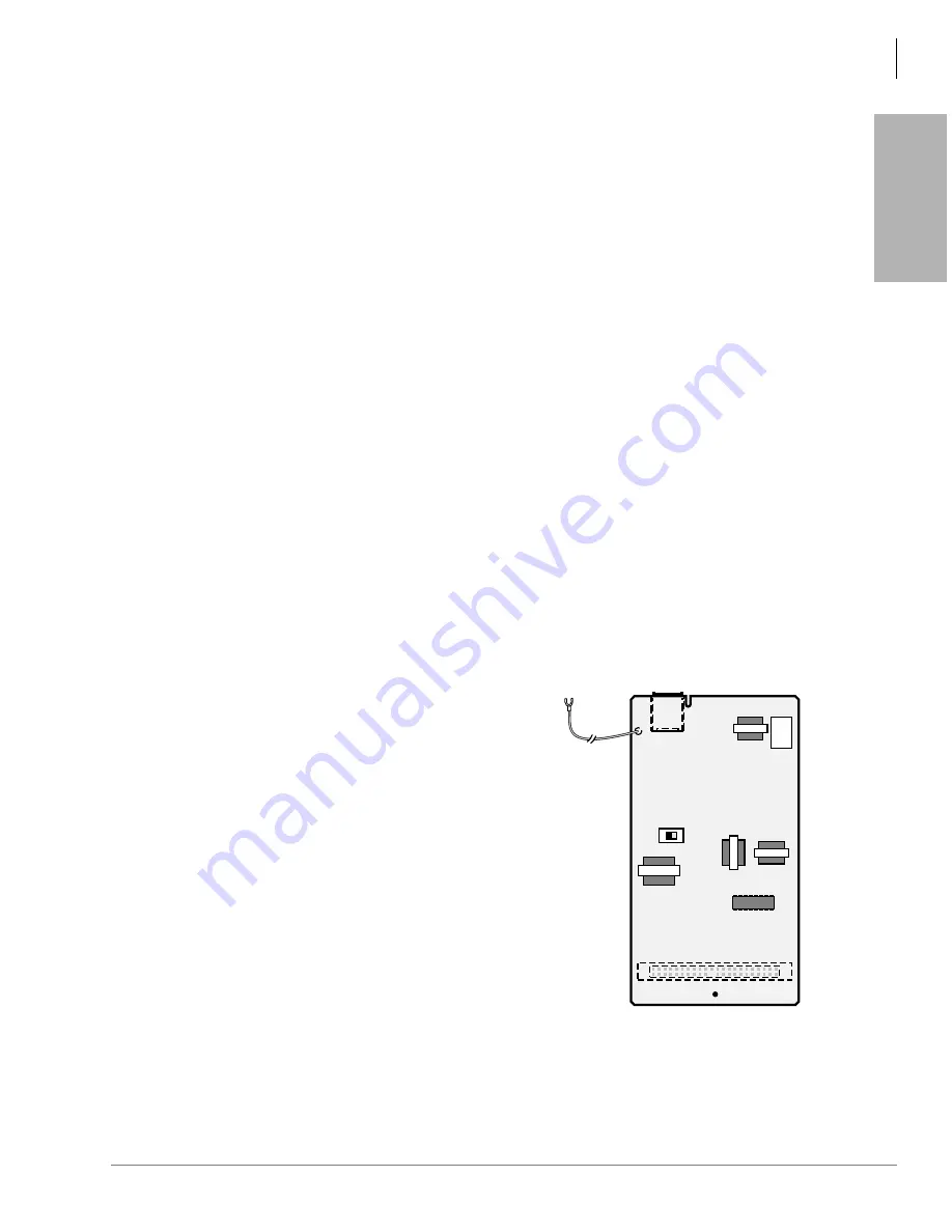
QCDU2 Configuration
The QCDU2 may have to be configured to control excessive loudness if the system is close to a
CO or installed behind a PBX telephone system. It does not have to be configured for anything
else. The decibel (db) PAD switch, SW101 controls the loudness by providing a 3 db signal level
drop to, or from, the PBX or CO when set to the PAD position. The switch comes from the factory
set at 0 (for no PAD) meaning no PAD loss.
QCDU2 Installation
A maximum of two QCDU2 PCBs can be installed in the KSU.
➤
To install the QCDU2
1. If the system is located within one mile of the CO or PBX telephone system, set db PAD
switch SW101 to the PAD position.
2. Make sure that the power supply switch is Off.
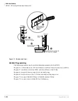
3. Slide QCDU2’s front edge and FG wire under the System Frame Ground Bar; align and insert
the QCDU2 connector J1 into the motherboard connector (J9 for CO3 first, J10 for CO4
second).
(See
Apply firm, even pressure to ensure proper
mating of the connectors. Make sure the
QCDU2’s connector edge next to the connector
J1 snaps firmly into the standoffs on the KSU
motherboard. (See
).
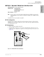
4. Connect the Frame Ground (FG) lead from the
QCDU2 to the screw nearest the QCDU2
located on the system Frame Ground bar.
Remove the “knock-out” from the KSU cover
CO3 or CO4 access slot, and store the “knock-
out” in the slots provided in the KSU base. (See
FG
J2
CO 3/4
0 PAD 3
SW101
2391
To System
Frame
Ground Bar
QCDU2A
J1
Figure 1-10 QCDU2 Printed Circuit
Board
Summary of Contents for Strata AirLink DK40i
Page 22: ...Introduction Related Documents Media xx Strata DK I M 6 00 ...
Page 48: ...DK14 Installation DK14 Wiring Diagrams 1 26 Strata DK I M 6 00 ...
Page 220: ...DK424 Installation Remote Cabinet Installation Instructions 5 68 Strata DK I M 6 00 ...
Page 262: ...DK424i Configuration Primary Reserve Power Cabinet Hardware 6 42 Strata DK I M 6 00 ...
Page 450: ...Universal Slot PCB Wiring Option Interface PCB Wiring Diagrams 10 42 Strata DK I M 6 00 ...
Page 592: ...Peripheral Installation Enhanced 911 Service E911 12 84 Strata DK I M 6 00 ...
Page 616: ...ACD Installation Spectrum Electronic Wall Boards 13 24 Strata DK I M 6 00 ...
Page 634: ...Fault Finding Fault Isolation Flowcharts 14 18 Strata DK I M 6 00 ...
Page 704: ...ISDN Interfaces ISDN Disconnect Cause Code 16 54 Strata DK I M 6 00 ...

