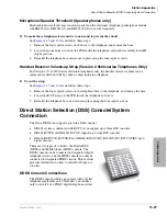
Station Apparatus
DKT2001 Digital Single Line Telephone
Strata DK I&M 6/00
11-15
Station Apparatus
DKT2001 Digital Single Line Telephone
The following provides information on how to connect the
DKT2001 Digital Single Line Telephones (SLTs) to the DK
system.
Before proceeding, see warning and caution notes in
The digital SLTs connect to the digital telephone ports via the
MDF with standard twisted-pair jacketed telephone cable. If
using 24 AWG cable, single-pair wiring is sufficient in most
cases for DKT2001 model standard telephones to operate
effectively at up to 1000 feet from the system.
To accommodate the digital telephone line cord, the cable
should be terminated in a modular station connector block
(RJ11) at the station location. The standard single-pair, modular DKT2001 model standard
telephone cord that is sent with the telephone is 7 ft. (the maximum allowed is 25 ft.).
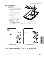
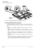
Digital telephone cable runs must not have cable splits (single or double), cable bridges (of any
length), or high resistance or faulty cable splices.
➤
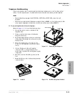
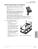
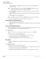
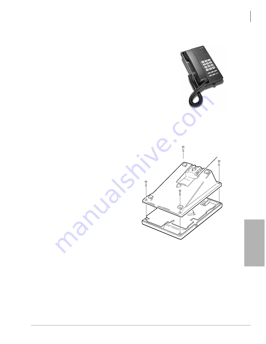
To wall mount DKT2001 digital SLTs
1. Loosen the screws, and remove the
telephone base.
2. Using a suitable cutter, remove the
handset hanger from the base.
3. Insert the handset hanger in the slot on
the front of the phone. The hanger fits
in the notch on the handset cradle.
4. Rotate the telephone base 180 degrees
and secure it to the telephone with its
four screws.
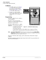
5. Connect the phone to the wall modular
connector with a cord approximately
four inches long (available at most
telephone supply companies).
6. Route the cord into the hollow portion
of the base.
7. Mount the phone on the wall mounting
modular connector plate.
3532
Handset Hanger
3633
Figure 11-12
Removing the Telephone Base
Summary of Contents for Strata AirLink DK40i
Page 22: ...Introduction Related Documents Media xx Strata DK I M 6 00 ...
Page 48: ...DK14 Installation DK14 Wiring Diagrams 1 26 Strata DK I M 6 00 ...
Page 220: ...DK424 Installation Remote Cabinet Installation Instructions 5 68 Strata DK I M 6 00 ...
Page 262: ...DK424i Configuration Primary Reserve Power Cabinet Hardware 6 42 Strata DK I M 6 00 ...
Page 450: ...Universal Slot PCB Wiring Option Interface PCB Wiring Diagrams 10 42 Strata DK I M 6 00 ...
Page 592: ...Peripheral Installation Enhanced 911 Service E911 12 84 Strata DK I M 6 00 ...
Page 616: ...ACD Installation Spectrum Electronic Wall Boards 13 24 Strata DK I M 6 00 ...
Page 634: ...Fault Finding Fault Isolation Flowcharts 14 18 Strata DK I M 6 00 ...
Page 704: ...ISDN Interfaces ISDN Disconnect Cause Code 16 54 Strata DK I M 6 00 ...


