DK424i Installation
Step 3: Ground the System
7-18
Strata DK I&M 6/00
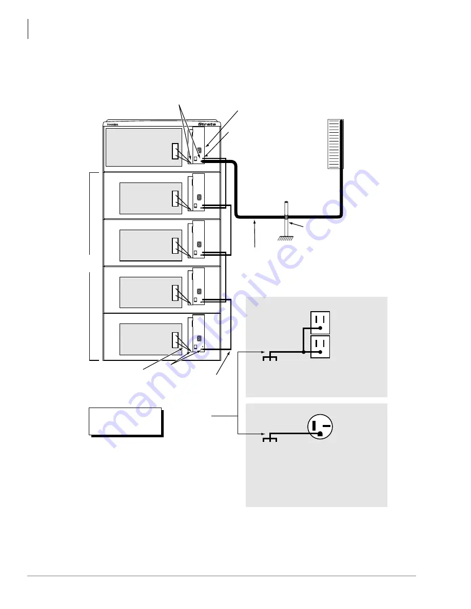
Figure 7-11 Cabinet Grounding
Cabinet Motherboard
Cabinet
Motherboard
Cabinet
Motherboard
Cabinet
Motherboard
Cabinet
Motherboard
FG Screws
Base
Cabinet
Power
Supply
FG (Frame Ground) Screws
The Single Point Ground must always be connected to
the Base Cabinet Power Supply FG Screw
(Top cabinet - Wall Mount or Bottom cabinet - Floor Mount.)
Expansion
Cabinets
Inter-cabinet green wires
supplied with each cabinet
Green/Green Yellow
ground wires from
Motherboard
Earth Ground:
AWG #6 Wire
(minimum)
Length: 60 Feet
(maximum)
Per General Rules of Article
250 of the National Electric
Code, NFPA70
ONEAC 6-AP
or 6-DP
Solid State
Secondary
Protectors
Third Wire
AC Ground
Insulated Ground Wire “B”
Note:
The impedance of the link
between point “A” and “B” must
be less than 0.25 ohms.
Note:
The ground must be
routed through the
same conduit as the
phase conductors
serving the system.
Single Point Ground (SPG)
Cold Water Pipe or Ground Rod
Note:
The SPG cannot be structural
steel members or conduit.
“A”
“A”
Note:
The impedance of
the link between
point “A” and “B”
must be less than
0.25 ohms.
Note:
The impedance of
the link between
point “A” and “B”
must be less than
0.25 ohms.
120VAC System Primary Power
Building Main Power
Panel Electrical Ground
208VAC ± 20VAC (50/60 Hz)
or 240VAC ± 20VAC (50/60 Hz)
Dedicated 20 Amp
Branch Circuit.
If 208VAC is used, the plug may have to be
changed by a licensed electrician.
Note:
The system may be
powered by 120, 208,
or 240VAC.
NEMA 6-20R,
240VAC
208 or 240VAC System Primary Power
115VAC ± 10VAC (50/60 Hz)
Dedicated 20 Amp
Branch Circuit
Building Main Power
Panel Electrical Ground
“B”
AWG #6 Wire
(minimum)
Length: 60 Feet
(maximum)
Point “B” is always on the
Base Cabinet, whether it's
on the top or bottom.
NEMA 5-15R,
120VAC
5044
The cabinets must be
located no more than 9
feet from the AC outlet.
Summary of Contents for Strata AirLink DK40i
Page 22: ...Introduction Related Documents Media xx Strata DK I M 6 00 ...
Page 48: ...DK14 Installation DK14 Wiring Diagrams 1 26 Strata DK I M 6 00 ...
Page 220: ...DK424 Installation Remote Cabinet Installation Instructions 5 68 Strata DK I M 6 00 ...
Page 262: ...DK424i Configuration Primary Reserve Power Cabinet Hardware 6 42 Strata DK I M 6 00 ...
Page 450: ...Universal Slot PCB Wiring Option Interface PCB Wiring Diagrams 10 42 Strata DK I M 6 00 ...
Page 592: ...Peripheral Installation Enhanced 911 Service E911 12 84 Strata DK I M 6 00 ...
Page 616: ...ACD Installation Spectrum Electronic Wall Boards 13 24 Strata DK I M 6 00 ...
Page 634: ...Fault Finding Fault Isolation Flowcharts 14 18 Strata DK I M 6 00 ...
Page 704: ...ISDN Interfaces ISDN Disconnect Cause Code 16 54 Strata DK I M 6 00 ...

