Universal Slot PCB Wiring
Cable Lengths
Strata DK I&M 6/00
10-17
Universal Slot
PCB
Wi
ri
n
g
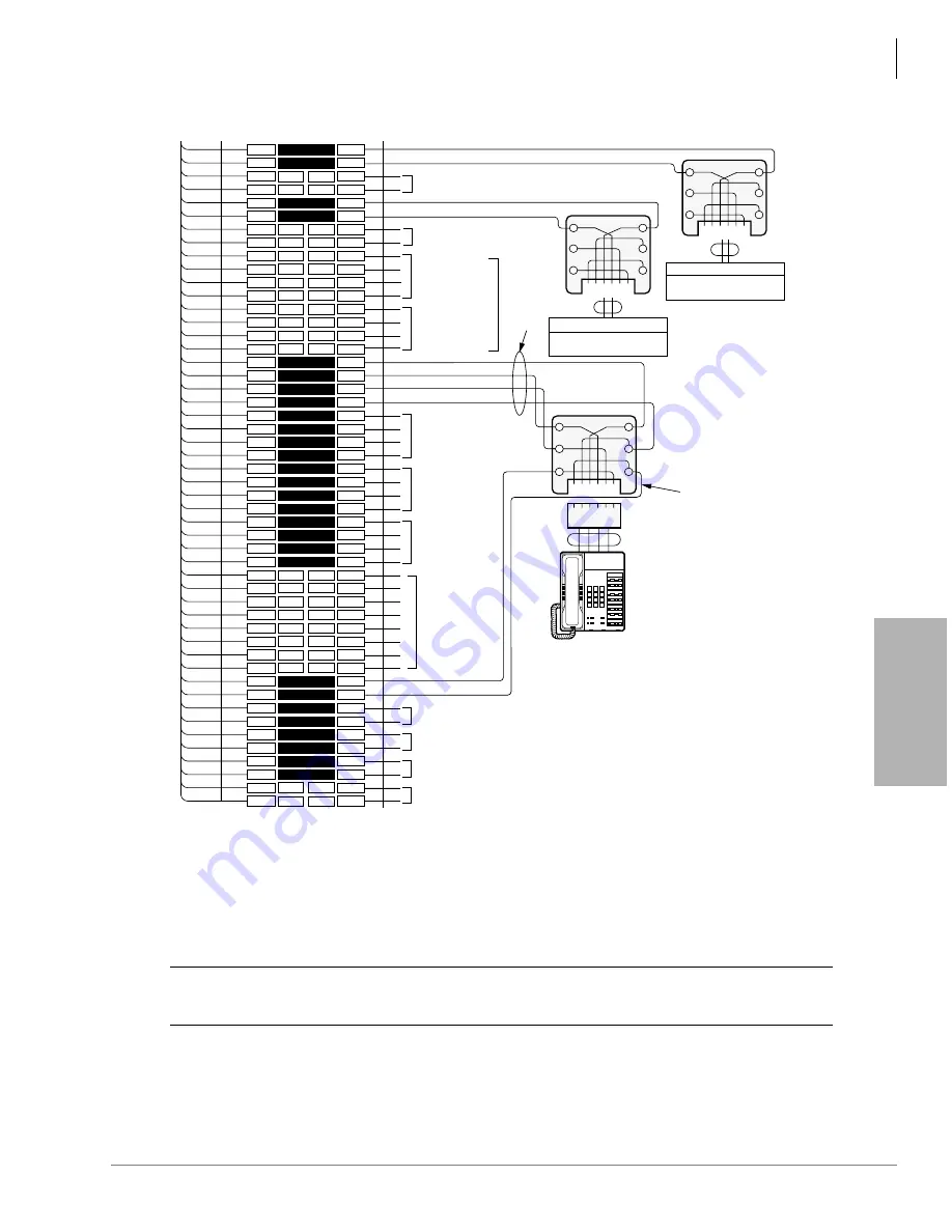
Figure 10-15 PEKU Station MDF Cross Connect Record PESU Wiring Diagram
1
2
3
4
5
6
7
8
9
10
11
12
13
14
15
16
17
18
19
20
21
22
23
24
25
26
27
28
29
30
31
32
33
34
35
36
37
38
39
40
41
42
43
44
45
46
47
48
49
50
1
2
3
4
5
6
7
8
9
10
11
12
13
14
15
16
17
18
19
20
21
22
23
24
25
26
27
28
29
30
31
32
33
34
35
36
37
38
39
40
41
42
43
44
45
46
47
48
49
50
W-BL
BL-W
W-O
O-W
W-GN
GN-W
W-BR
BR-W
W-S
S-W
R-BL
BL-R
R-O
O-R
R-GN
GN-R
R-BR
BR-R
R-S
S-R
BK-BL
BL-BK
BK-O
O-BK
BK-GN
GN-BK
BK-BR
BR-BK
BK-S
S-BK
Y-BL
BL-Y
Y-O
O-Y
Y-GN
GN-Y
Y-BR
BR-Y
Y-S
S-Y
V-BL
BL-V
V-O
O-V
V-GN
GN-V
V-BR
BR-V
V-S
S-V
26
1
27
2
28
3
29
4
30
5
31
6
32
7
33
8
34
9
35
10
36
11
37
12
38
13
39
14
40
15
41
16
42
17
43
18
44
19
45
20
46
21
47
22
48
23
49
24
50
25
Bridging Clips
To PESU w/Female
Connector
25-Pair Cable w/Male amp Connector
66M150 Split Block
Circuit 3
Not Used
Circuit 4
Not Used
Circuit 6
to EKT 2
Circuit 8 to
EKT 4
or BGM
(see Notes)
OCA T1 (OT) 5
OCA R1 (OR) 5
VT
VR
DT
DR
Tip 1
Ring 1
GN
Y
BL
R
BK
W
Not Used
Not Used
(Port count
in software)
6 5 4 3 2 1
6 5 4 3 2 1
GN
6 5 4 3 2 1
Y
BL
R
BK
W
1 2 3 4 5 6
24
AWG
Modular
Cord
Station
DT
OCAT
OCAR
DR
VR
VT
RJ11
OT and OR:
Only if
EKT
Receives
OCA Calls
Voice Mail Port or
Similar Device
Voice Mail Port or
Similar Device
RJ11
RJ11
VT
VR
DT
DR
VT
VR
DT
DR
OT
OR
OT
OR
OT
OR
Voice T1 (VT) 5
Voice R1 (VR) 5
Data T1 (DT) 5
Data R1 (DR) 5
Ring
Tip
Tip
Ring
Standard Telephone 2
Standard Telephone 1
Ring 2
Tip 2
Circuit 7 to
EKT 3
GN
Y
BL
R
BK
W
Strap Options:
W9 - Cut if HDCB is connected to Circuit 5
P90 - Ring Voltage Option Circuit 1 & 2):
L = Low Level (130VDC P-P)
H = High Level (190VDC P-P)
Not Used
Not Used
Circuit 6
Circuit 7
Circuit 8
EKT 1 or HDCB
See Program 77-1
Station Cabling Jacketed Pairs (24 AWG)
Notes
(Standard telephone circuits 1 & 2)
•
All cable 24 AWG; max loop resistance - 300 ohms from PESU
to standard telephone/VM port.
•
Standard telephones may be on- or off-premises. Off-premises
connection is made via OL13A FIC, and RJ21X jack.
•
Two ringers max per port.
1585
Notes
•
Two-ringers max may be connected (high or low) to Tip/Ring.
HDSS connection is not available with PESU; HDCB may be
connected to circuit 5, BGM to circuit 8 (see Program 77-1).
(Electronic telephone circuits 5~8)
•
To receive OCA, the 6500-series EKT must have an HVSU2 or
the combined HVSI and HVSU installed.
•
Program 31, button/LED 03 must be ON for the EKT to receive
OCA.
•
An HHEU must be installed inside 6500-series EKTs for
headset or HESB; Loud Ringing Bell option.
•
All cable 24 AWG, max 40 ohm loop resistance from PESU to
electronic telephone (1000 ft).
CAUTION!
To prevent system malfunction, DO NOT install the PESU in Slot 18 of the
DK40i system.
Summary of Contents for Strata AirLink DK40i
Page 22: ...Introduction Related Documents Media xx Strata DK I M 6 00 ...
Page 48: ...DK14 Installation DK14 Wiring Diagrams 1 26 Strata DK I M 6 00 ...
Page 220: ...DK424 Installation Remote Cabinet Installation Instructions 5 68 Strata DK I M 6 00 ...
Page 262: ...DK424i Configuration Primary Reserve Power Cabinet Hardware 6 42 Strata DK I M 6 00 ...
Page 450: ...Universal Slot PCB Wiring Option Interface PCB Wiring Diagrams 10 42 Strata DK I M 6 00 ...
Page 592: ...Peripheral Installation Enhanced 911 Service E911 12 84 Strata DK I M 6 00 ...
Page 616: ...ACD Installation Spectrum Electronic Wall Boards 13 24 Strata DK I M 6 00 ...
Page 634: ...Fault Finding Fault Isolation Flowcharts 14 18 Strata DK I M 6 00 ...
Page 704: ...ISDN Interfaces ISDN Disconnect Cause Code 16 54 Strata DK I M 6 00 ...


