DK424 Installation
RCTUA, RCTUBA/BB, RCTUC/D, RCTUE/F Common Control Units
Strata DK I&M 6/00
5-55
DK424 Installa
tion
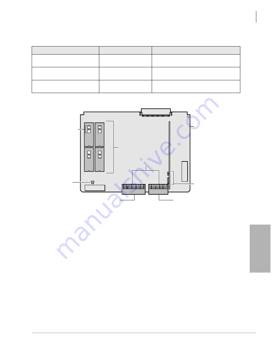
Table 5-9
RCTUBB Controls, Indicators, and Interface Connectors
Control/Indicator/Connector
Type of Component
Description
Connector P2
Connector for ribbon
cables
Connector for RCTUBA ribbon cables. Used
with P2.
Connector P3
Connector for ribbon
cables
Connector for RCTUBA and RSIU ribbon
cable. Used with P11.
Heart Beat indicator CD11
Red LED
Flashes to indicate operation (1/4 second On
— 1/4 second Off).
Figure 5-34 RCTUBB PCB
Backplane Connector
IC10
P1
Program
ROMS
IC9, 10, 11, and 12
To RCTUBA/RSIU
Connectors
CD5
RCTUBB4
CBRUK
Heart Beat
LED
P3
P2
IC9
U3
RKYS
Key Socket
Ribbon Cable to RCTUBA
(and RSIU if installed)
Ribbon Cable to RCTUBA
Install in
“RCTU” Slot
RBA3-0
Identifies
ROM Version
RBA3-9
RBA3-2
RBA3-1
IC12
IC11
RCTUBB4
1368
Summary of Contents for Strata AirLink DK40i
Page 22: ...Introduction Related Documents Media xx Strata DK I M 6 00 ...
Page 48: ...DK14 Installation DK14 Wiring Diagrams 1 26 Strata DK I M 6 00 ...
Page 220: ...DK424 Installation Remote Cabinet Installation Instructions 5 68 Strata DK I M 6 00 ...
Page 262: ...DK424i Configuration Primary Reserve Power Cabinet Hardware 6 42 Strata DK I M 6 00 ...
Page 450: ...Universal Slot PCB Wiring Option Interface PCB Wiring Diagrams 10 42 Strata DK I M 6 00 ...
Page 592: ...Peripheral Installation Enhanced 911 Service E911 12 84 Strata DK I M 6 00 ...
Page 616: ...ACD Installation Spectrum Electronic Wall Boards 13 24 Strata DK I M 6 00 ...
Page 634: ...Fault Finding Fault Isolation Flowcharts 14 18 Strata DK I M 6 00 ...
Page 704: ...ISDN Interfaces ISDN Disconnect Cause Code 16 54 Strata DK I M 6 00 ...


