Universal Slot PCB Wiring
Cable Lengths
Strata DK I&M 6/00
10-13
Universal Slot
PCB
Wi
ri
n
g
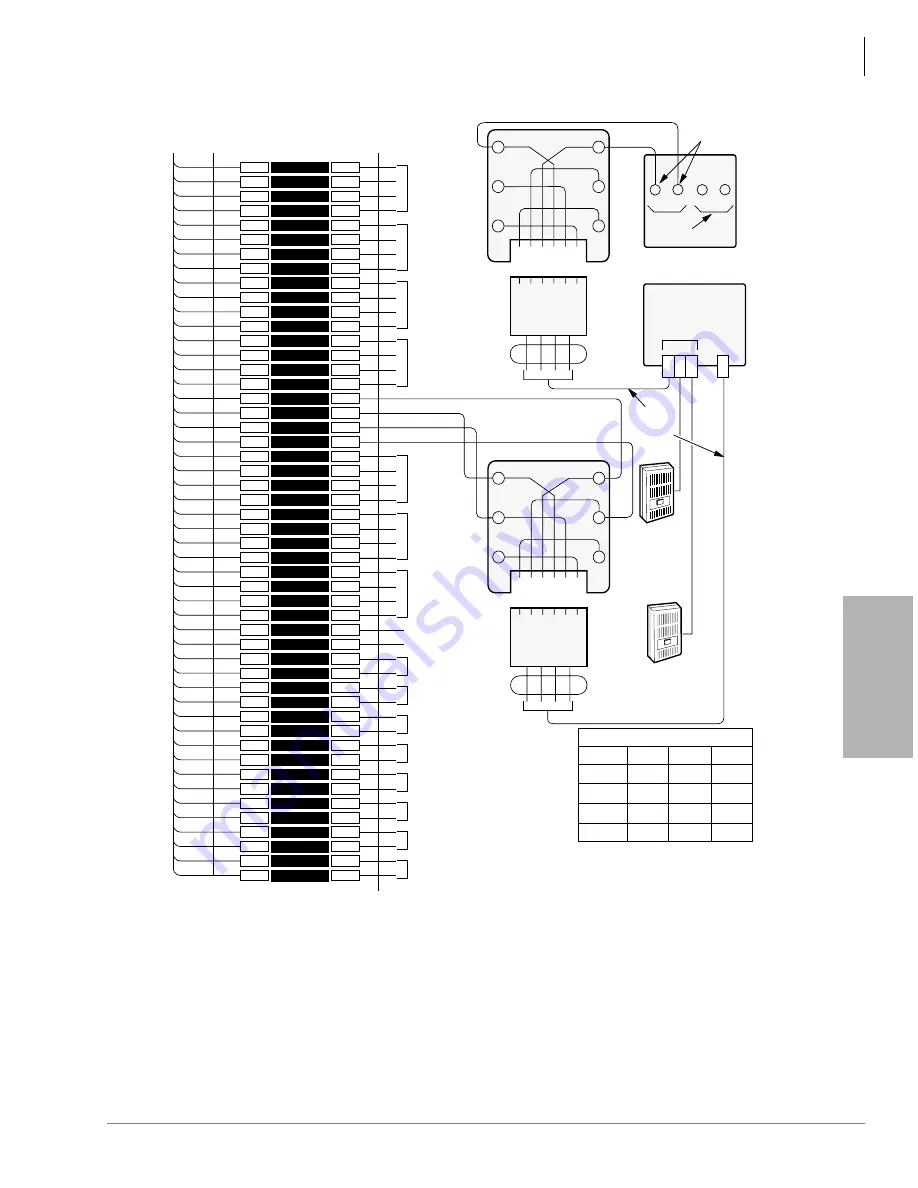
Figure 10-11
MDF Wiring-Door Phone/Lock to PEKU/PESU
1
2
3
4
5
6
7
8
9
10
11
12
13
14
15
16
17
18
19
20
21
22
23
24
25
26
27
28
29
30
31
32
33
34
35
36
37
38
39
40
41
42
43
44
45
46
47
48
49
50
1
2
3
4
5
6
7
8
9
10
11
12
13
14
15
16
17
18
19
20
21
22
23
24
25
26
27
28
29
30
31
32
33
34
35
36
37
38
39
40
41
42
43
44
45
46
47
48
49
50
W-BL
BL-W
W-O
O-W
W-GN
GN-W
W-BR
BR-W
W-S
S-W
R-BL
BL-R
R-O
O-R
R-GN
GN-R
R-BR
BR-R
R-S
S-R
BK-BL
BL-BK
BK-O
O-BK
BK-GN
GN-BK
BK-BR
BR-BK
BK-S
S-BK
Y-BL
BL-Y
Y-O
O-Y
Y-GN
GN-Y
Y-BR
BR-Y
Y-S
S-Y
V-BL
BL-V
V-O
O-V
V-GN
GN-V
V-BR
BR-V
V-S
S-V
26
1
27
2
28
3
29
4
30
5
31
6
32
7
33
8
34
9
35
10
36
11
37
12
38
13
39
14
40
15
41
16
42
17
43
18
44
19
45
20
46
21
47
22
48
23
49
24
50
25
Bridging
Clips
To PEKU or PESU
w/Female Connector
25 Pair Cable w/Male amp Connector
66M150 Split Block
Circuit 2
Circuit 3
Circuit 4
Circuit 5
Circuit 6
Circuit 7
Circuit 8
Not Used
Circuit 2
Circuit 3
Circuit 4
Circuit 6
Circuit 7
Circuit 8
OCA T1
OCA R1
GN
6 5 4 3 2 1
Y
BL
R
BK
W
2 3 4 5
Modular
Cord
GN
6 5 4 3 2 1
Y
BL
R
BK
W
3 4
Modular
Cord
1
2
L1
L2
Not
Used
A B C
Door Phone
MDFB
HDCB
HKSU
MDFB
Door
Phone B
or Door
Lock
Control
MDFB
Door
Phone C
See Note 1
See Note 2
MDFB (Rear View)
2-Pair
Modular
Cords
Voice T5
Voice R5
Data T5
Data R5
Screw
Terminals
Door Phone A
Port #
004
012
020
028
A
151
154
157
161
B
152
155
158
162
C
153
156
159
163
MDFB (Door Phone) Station Nos.
VR
VT
DR
DT
Circuit 1
See Note 1
Notes
1. On PEKU or PESU, cut W9. See Programs 39, 77-1, 77-2, and 79.
2. HDCB “B” output options:
SW1: Always in DOOR position.
SW2: DOOR position; “B” connects to door phone LOCK position;
“B” connects to door lock.
3. Door phones may be connected to Circuit 5 on Ports 004, 012, 020,
and 028 only.
1580
Summary of Contents for Strata AirLink DK40i
Page 22: ...Introduction Related Documents Media xx Strata DK I M 6 00 ...
Page 48: ...DK14 Installation DK14 Wiring Diagrams 1 26 Strata DK I M 6 00 ...
Page 220: ...DK424 Installation Remote Cabinet Installation Instructions 5 68 Strata DK I M 6 00 ...
Page 262: ...DK424i Configuration Primary Reserve Power Cabinet Hardware 6 42 Strata DK I M 6 00 ...
Page 450: ...Universal Slot PCB Wiring Option Interface PCB Wiring Diagrams 10 42 Strata DK I M 6 00 ...
Page 592: ...Peripheral Installation Enhanced 911 Service E911 12 84 Strata DK I M 6 00 ...
Page 616: ...ACD Installation Spectrum Electronic Wall Boards 13 24 Strata DK I M 6 00 ...
Page 634: ...Fault Finding Fault Isolation Flowcharts 14 18 Strata DK I M 6 00 ...
Page 704: ...ISDN Interfaces ISDN Disconnect Cause Code 16 54 Strata DK I M 6 00 ...


