T1
Performance Monitoring
8-16
Strata DK I&M 6/00
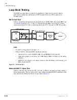
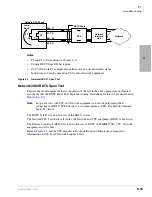
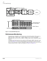
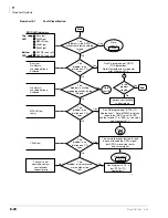
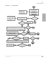
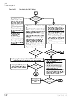
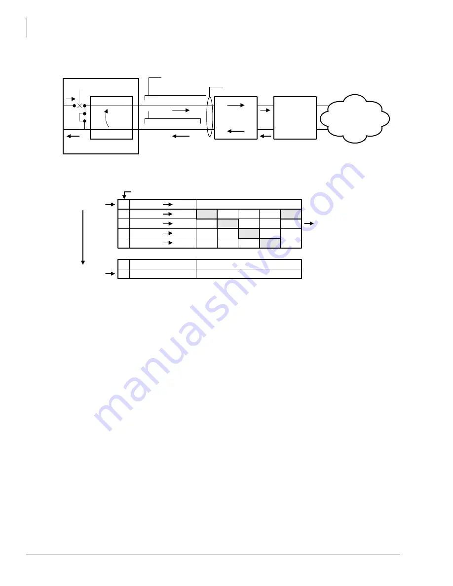
Figure 8-10 Network/CSU/RDTU Span Test
Performance Monitoring
The performance of the RDTU can be monitored using the Data Dump Mode. This requires an
RSIU, RSIS, PIOU or PIOUS PCB, an ASCII terminal (or PC) and, if monitoring RDTU
performance from a remote location, an IMDU or RMDS modem or Hayes compatible modem is
required.
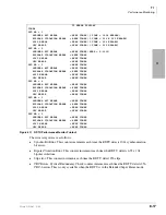
The RDTU monitoring feature provides a printout (or CRT display) of RDTU detected T1 errors
as shown in
. There are no time parameters given with this error report so the time
between error count increments must be monitored manually. Basically the error count of any error
category should not increase within 24-hour periods (see
).
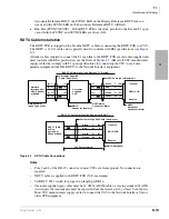
RDTU
RDTU TX Open
MITEL Chip
P4
MM8976B
P1/P26 Transmit
P2/P27 Receive
NDTU Cable
RDTU Amphenol Pin Nos.
Network
CSU
Network
Interface
Unit (NIU)
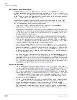
2581
Top LED
Bottom LED
T = About 1/2 Second
Continue to Cycle when
P4 is in ON Position
0
0
0
0
0
ON Steady
ON
OFF
OFF
OFF
OFF
ON
OFF
OFF
OFF
OFF
ON
OFF
OFF
OFF
OFF
ON
ON
OFF
OFF
OFF
Busy
FALM
FMALM
YALM
BALM
T1
T2
T3
T4
T5
0
0
ON or OFF, Steady
ON or OFF, Steady
Primary SYNC
Secondary SYNC
LEDS ON RDTU PCB
T6
1673
Summary of Contents for Strata AirLink DK40i
Page 22: ...Introduction Related Documents Media xx Strata DK I M 6 00 ...
Page 48: ...DK14 Installation DK14 Wiring Diagrams 1 26 Strata DK I M 6 00 ...
Page 220: ...DK424 Installation Remote Cabinet Installation Instructions 5 68 Strata DK I M 6 00 ...
Page 262: ...DK424i Configuration Primary Reserve Power Cabinet Hardware 6 42 Strata DK I M 6 00 ...
Page 450: ...Universal Slot PCB Wiring Option Interface PCB Wiring Diagrams 10 42 Strata DK I M 6 00 ...
Page 592: ...Peripheral Installation Enhanced 911 Service E911 12 84 Strata DK I M 6 00 ...
Page 616: ...ACD Installation Spectrum Electronic Wall Boards 13 24 Strata DK I M 6 00 ...
Page 634: ...Fault Finding Fault Isolation Flowcharts 14 18 Strata DK I M 6 00 ...
Page 704: ...ISDN Interfaces ISDN Disconnect Cause Code 16 54 Strata DK I M 6 00 ...


