


3 Specifications
3 - 34
AC Servomotors/Servo Drives 1S-series with Built-in EtherCAT® Communications User’s Manual (I586)
Note When you do not use the STO function via safety input signals, short-circuit pins 22 and 23, 24 and 26, 3
and 5, and 6 and 7.
When you use the STO function via safety input signals, remove the attached short-circuit wires and do not
connect anything to pins 7 and 22.
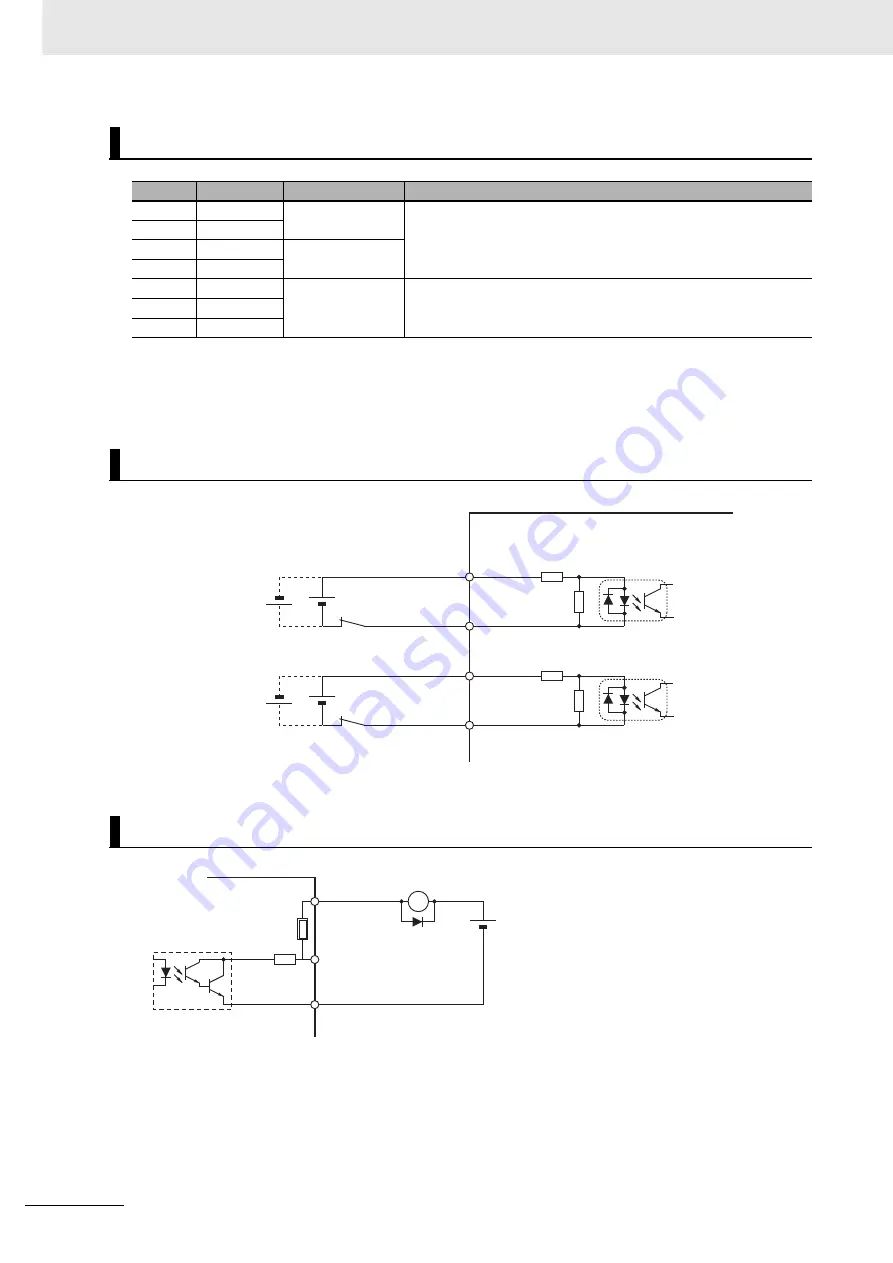
*1. When you use an output signal to drive a relay directly, always insert a diode as shown in the above figure.
Use a high-speed diode.
Safety I/O Signal Table
Pin No.
Symbol
Name
Function and interface
3 and 23
SF1+
Safety input 1
Inputs 1 and 2 for operating the STO function, which are two inde-
pendent circuits. This input turns OFF the power transistor drive
signals in the Servo Drive to cut off the current output to the motor.
4 and 24
SF1-
5 and 25
SF2+
Safety input 2
6 and 26
SF2-
1
EDM+ P
EDM Output
A monitor signal is output to detect a safety function failure.
2
EDM+
21
EDM-
Safety Input Circuits
EDM Output Circuit
4.3 kΩ
430 Ω
24 VDC±5%
4.3 kΩ
430 Ω
SF1+
3, 23
SF1-
4, 24
SF2+
5, 25
SF2-
6, 26
Photocoupler input
External power
supply
Photocoupler input
Servo Drive
Signal level
ON level: 20.8 V or more
OFF level: 5 V or less
X
21 EDM-
2 EDM+
1 EDM+P
Di
2.2
Ω
Servo Drive
External power supply
12 to 24 VDC
Maximum service voltage: 30 VDC
Maximum output current: 50 mA
Leakage current: 1 mA or less
Residual voltage:
Di: Surge voltage prevention diode
*1
Short-circuit
protection element
2.0 V or less (EDM+P)
1.7 V or less (EDM+)
Summary of Contents for R88D-1SN ECT Series
Page 973: ......