background image

[Save Form Information]

This is used when saving the form information that is contained in the P-PRINTER 
printer driver.
All of the selection values displayed in the [Form Name] pull-down list will be saved 
in a file.

File Name  :  This shows the destination folder for saving the file.
Browse…  :  This specifies the destination folder for saving the form information 

file, and inputs the file name.

Save 

:  This saves the form information file under the name that was input in 

[File Name].

[Load Form Information]

This is used when loading form information that has been saved using [Save Form 
Information].

File Name  :  This displays files that contain form information for loading.
Browse…  :  This  specifies  the  loading  destination  folder  of  the  form  information 

files, and selects the form information file.

Load 

:  This  loads  the  form  information  file  displayed  in  [File  Name]. The 

loaded  information  will  be  displayed  in  the  [Main]  tab  [Form  Name] 
pull-down list, allowing the names to be selected.

About:  This  allows  confirmation  of  the  printer  driver  version  and  the  copyright 

information. When this is clicked, the [About] dialog box will be displayed.


Reference


Refer  to “About”  in “3.4  Method  of  Using  the  Printer  Driver” 
on P.74.


• The file name extension will be **.txt.

3.4 Method of Using the Printer Driver

69

Summary of Contents for M-350

Page 1: ...M 350 User s Guide...

Page 2: ...d Clear Printing on Plates Direct printing is possible on rigid plastic plates acrylic and PVC and mirror printing can be carried out on clear plates so that sharp printing can be done swiftly and eas...

Page 3: ...s guide Warning This describes warnings that may lead to death or serious injury in the situation where the product is mishandled To allow safe use of the product be certain to observe these warnings...

Page 4: ...Use the menu cleaning mode depending on the condition of the roller 1 Press the Online key to set the printer to Offline The online lamp will switch off 2 Press the Menu key Menu Cleaning is displayed...

Page 5: ...ta Abbreviated as Windows Vista Microsoft Windows 7 Abbreviated as Windows 7 Regulations for this product FCC Regulations This device complies with Part 15 of the FCC Rules Operation is subject to the...

Page 6: ...ury Do not install the printer in locations with high humidity or large amounts of dust and keep it away from sources of high temperatures or fire since it may cause fire or electric shock Do not inst...

Page 7: ...earthed socket Use with an AC100 240V 50 60Hz power source Do not use at other voltages since this may result in fires electric shock or breakdowns Do not switch on the power while the power cord is s...

Page 8: ...will result in fire electric shock or breakdowns In the situation where abnormalities occur such as when there is a strange sound when smoke appears or if there is a strange odor immediately switch o...

Page 9: ...ssette and cleaning cassette Temperature C Humidity Operating Environment 15 32 5 10 85 Storage Environment 5 35 10 90 In the case where the product will not be used for some time such as overnight sw...

Page 10: ...splay Data Receiving Message 21 2 Operation Panel Menu Mode Configuration 22 2 2 Connecting the Power Cord 24 2 3 Setting the Cleaning Cassette 25 2 4 Setting the Ribbon Cassette 29 2 5 Switching On a...

Page 11: ...ot in Use 78 To Change the Language shown on the Display 79 To Increase the Printing Speed 79 To Change the Timing for Cleaning the Cleaning Roller 80 To Clean the Cleaning Roller 80 To Implement Test...

Page 12: ...e not Ejected 91 4 3 Printer Messages 92 Notification Messages 92 Breakdown Messages 93 4 4 Routine Cleaning 94 Cleaning the Cleaning Roller 94 Other Cleaning Locations 97 Replacement Parts 97 4 5 Pla...

Page 13: ...se In this chapter explanations are given of the accessories included with the product and the names of the parts 13 1 1 Confirmation of Accessories 14 Packing Materials 14 1 2 Names of Main Unit Part...

Page 14: ...ld be stored They will be required when sending the printer such as in situations where repairs are necessary Printer Main Unit Cleaning Cassette Ribbon Cassette Black Printer Driver and Operation Man...

Page 15: ...tte Mounting Part This is the mounting part for the ribbon cassette P 29 4 Feeding Roller This ejects the media after printing P 9 P 97 5 Print Head This is the head that prints on the media P 87 P 97...

Page 16: ...erval 10mm 14 Tray Support This supports the tray P 31 P 35 15 Tray Long media is placed on here P 31 P 35 16 Power Switch This switches on and off the printer power P 30 17 Roll Holding Rollers These...

Page 17: ...hed power cord here P 24 2 Ventilation Holes These expel the heat from inside the printer P 6 3 USB Cable Insertion Port Insert the attached USB cable here P 48 4 Media Ejection Port The media is ejec...

Page 18: ...tte 25 2 4 Setting the Ribbon Cassette 29 2 5 Switching On and Off the Power Switch 30 When Switching On 30 When Switching Off 30 2 6 Setting the Plates 31 Tag Plates with Holes 34 2 7 Setting the Rol...

Page 19: ...rinting is not possible and when the printer is giving notification of a message Details Cover open Check Media No Ribbon Printer inside is hot Please wait No cleaning tape Replace Ribbon Cassette Med...

Page 20: ...Press this in the standby condition Offline to change to the Menu Selection mode After selecting the menu this displays the menu items by acting as the key In the situation where Remove has been selec...

Page 21: ...h of Printing Media 5 Printing Density 6 Number of Copies 2 1 Operation Panel Component Names and Operations Display 1 Color R Red B Blue or K Black 2 Feeding Method Manu Manual or Auto Continuous 3 T...

Page 22: ...to 5 Bright FEED CUT PRINT Quality Speed 1 02 to 1 02 mm 5 0 to 5 0 Plate Sheet Long Plates Short Plates 22 2 1 Operation Panel Component Names and Operations Select this item to set the timing for t...

Page 23: ...l Enter Menu English French Spanish German Italian Menu Menu Cancel 23 2 1 Operation Panel Component Names and Operations Select this item to set the time until the power automatically switches off P...

Page 24: ...n port on the rear face of the printer 2 Insert the plug of the power cord into an AC100 240V power socket that is properly earthed Security Cable Lock 1 Regarding the handling of the power cord pleas...

Page 25: ...so that there will be a danger of damaging the print head 1 Open the cover In the situation where the cleaning cassette is to be set first remove the ribbon cassette If the cleaning cassette is set w...

Page 26: ...iary roller and set the cleaning cassette aligned with the guide hook Cleaning Tape Guide Hook Cleaning Auxiliary Roller Cleaning Cassette Tape Pulling out Direction After setting the cleaning cassett...

Page 27: ...where the tape is not tensioned lower the setting lever to release the locking of the cleaning auxiliary roller and remove the cleaning cassette Then wind in the cleaning tape to eliminate the tape sl...

Page 28: ...The locking of the cleaning auxiliary roller will be released Setting Lever Cleaning Auxiliary Roller Take care that if the cleaning cassette is removed without first releasing the locking of the clea...

Page 29: ...he ribbon Eliminate any slackness in the ribbon 2 Set the ribbon cassette after setting the cleaning cassette 3 Close the cover If the cover is closed while the ribbon cassette is in a floating condit...

Page 30: ...efore turning on the switch please be sure that there is no media inside the printer If media is left inside remove it out from the printer In case media is left especially close to the printer therma...

Page 31: ...or longer pull out the plate guide When not using the guide return it to its previous position 2 Confirm that the operation panel display shows Plate Black Plate Printing ready Reference Refer to 4 1...

Page 32: ...or PVC that are 3mm or less in thickness Note that among commercially available plates there are some that will not allow normal printing using this printer For more details please contact your neares...

Page 33: ...Move the width regulating guide until it is lightly touching the plate Adhesive attached to the width regulating guide may cause feeding problems If adhesive soiling is noticed on the width regulating...

Page 34: ...pletely finished If you insert another new plate while printing It may cause damage inside the printer including the printer thermal head or the rollers Tag Plates with Holes Hole position and dimensi...

Page 35: ...ay do not feed in the roll sheet Correct feeding will not be possible When Plate is selected set the offline condition and select Sheet from the Media Selection menu item Depending on the printing sur...

Page 36: ...ll be required during storage and handling Please note in advance that it will require extreme care not to damage the print head by printing with these types of sheets Clear printing will not be possi...

Page 37: ...double beep is heard please carry out the sheet setting procedure again Feeding Port Carry out the printing setting in the PC as follows Sheet Glossy Plain Die Cut Label TOF Label Reference Refer to...

Page 38: ...r on P 64 1 Continuous Roll Sheet Glossy Plain Diameter 140mm or less Diameter 76mm or more 3 inch paper tube etc Width 40 80mm 2 Die Cut Sheet Rolls Die Cut Labels Among the commercially available di...

Page 39: ...f the adhesive surface is exposed In this situation use the sheet after cutting off the leading edge of the sheet Using the sheet with the exposed adhesive surface may result in damage to the printer...

Page 40: ...be taken out After printing the media is normally ejected However in the situation where the media remains in the printer without being ejected use the Remove function to remove the media Reference Re...

Page 41: ...isplayed 2 Using scissors cut off the printed segment at right angles In the situation of sheets that are half cut or have perforations bend the sheet along the fold line and detach the segment If the...

Page 42: ...Printer 51 Preparations 51 Data Creation 51 Printing 54 Halting the Printing 55 3 3 Single Color Printing 56 Single Color Printing 58 3 4 Method of Using the Printer Driver 64 Methods of Displaying t...

Page 43: ...Vista 32 64 bit XP 32 bit Installation An explanation is given using the example of installing on Windows 7 Do not connect the USB cable to the computer before the printer driver has been installed Af...

Page 44: ...drive icon 3 Double click on setup exe When using Windows Vista 1 Select Computer from the Windows Start menu The Computer folder will be displayed 2 Click on the CD ROM drive icon 3 Double click on...

Page 45: ...f Print is clicked the software license agreement will be printed out from the default printer which has been set in Windows 7 Following the instructions on the screen click on Install If the followin...

Page 46: ...ted without restarting the PC there will be a risk that the program may not operate normally You need to log on as an Administrator or a user with administrator s authority on the computer after reboo...

Page 47: ...y Recommended is selected and click on Next 13 If the following screen is displayed click on Continue Anyway 14 When the following screen is displayed click on Finish The above procedure completes the...

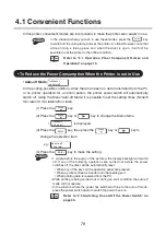
Page 48: ...le the PC and printer power is on However in the following situations correct operation may not be possible so connection and removal should not be carried out While the PC is starting up or when data...

Page 49: ...rinter use the following procedure 1 Confirm that the printer is not operating 2 Switch off the printer power switch then remove the USB cable 3 Using the following procedures uninstall the printer dr...

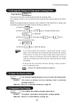
Page 50: ...be displayed 3 Click on P PRINTER then click on Delete 4 When the following screen is displayed click on Remove then click on Next 5 When the following screen is displayed click on Yes 6 When the foll...

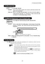
Page 51: ...er the printer driver installation and the printer connection has been completed the printing preparation should be completed Reference Refer to 3 1 Installing the Printer Driver on P 43 2 2 Connectin...

Page 52: ...rm size in the list before creating the data Reference Refer to Setting the Form Setting Tab in 3 4 Method of Using the Printer Driver on P 67 Page Setup Left 10mm Right 10mm Top 5mm Bottom 5mm The mi...

Page 53: ...ntents have been set using the printer operation panel and the PC application and printer driver the settings of the side that were made last will be effective Take care particularly in situations whe...

Page 54: ...dPad Print dialog box will be displayed 4 Confirm that P PRINTER is selected in Select Printer and click on Preferences The P PRINTER Printing Preferences screen will be displayed 5 Carry out the prin...

Page 55: ...printing is taking place By pressing the Cancel key for 3 seconds or longer it will be possible to abandon the printing In the situation where the key is pressed while printing is being carried out th...

Page 56: ...f printing multiple colors on top of each other can also not be guaranteed For the colors during editing please use the three colors red blue and black If data for light colors or intermediate colors...

Page 57: ...of printing on die cut labels canceling of the ribbon color cannot be carried out Please set the ribbon color as indicated on the display 6 When the printing of the color of the color ribbon cassette...

Page 58: ...olors or intermediate colors is created the colors on the PC screen may differ from the colors that are actually printed so please create the data using the red blue and black colors In order to print...

Page 59: ...s Color Mode One Mirror Printing Off Density 3 Reference In the situation where you wish to register a form size or to change the printing settings to match a particular purpose refer to 3 4 Method of...

Page 60: ...place the ribbon cassette with a new one 9 Press the Enter key Printing will start from the color of the ribbon cassette that is set in the printer When the printing finishes a message requesting repl...

Page 61: ...the plate will be ejected 12 When the printing of the second color finishes the Replace the ribbon cassette message will be displayed 13 Set the plate that has had the second color printed back in the...

Page 62: ...printing of the first color of the first copy will be carried out When the printing finishes the first plate will be ejected 6 When Set a new media is displayed set the second plate in the printer Th...

Page 63: ...copies Many Copies Printing is carried out one color at a time 5 Carry out the printing of the first color of the first copy When the printing finishes the printing will continue of the first color o...

Page 64: ...n Generally selecting Print from the File menu will allow the Print Settings dialog box to be opened 2 Select P PRINTER and click on Properties or Advanced Settings The printer driver settings screen...

Page 65: ...or the printing and is set to Portrait or Landscape Media Type This sets the printing media to Plate or Sheet and the qualities of these materials are selected from a pull down list For plates qualiti...

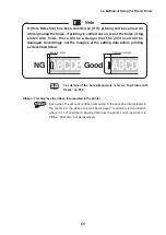
Page 66: ...editing data before printing as described below Margin 2mm ABCDE ABCDE Optional margin Reference For details of the hole dimensions refer to Tag Plates with Holes on P34 Ribbon This displays the ribb...

Page 67: ...isplayed in Form Name Add Edit This displays the dialog box that sets the name and size of the form that will be used for the printing Method of Registering Forms 1 Input the name of the printing medi...

Page 68: ...leting a Form 1 Select the printing media that you wish to delete from the Form Name pull down list 2 Confirm that the sizes shown in Width and Length match the size of the printing media that you wis...

Page 69: ...ion that has been saved using Save Form Information File Name This displays files that contain form information for loading Browse This specifies the loading destination folder of the form information...

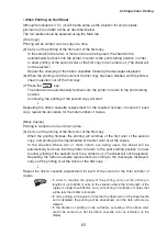
Page 70: ...een selected density setting is possible for each color The Density setting is not normally changed and should be left set to 3 Please change the setting if the printing has become too faint or too da...

Page 71: ...rence Refer to About in 3 4 Method of Using the Printer Driver on P 74 Status This displays the M 350 condition and messages Media This displays the type of media that has been set Width This displays...

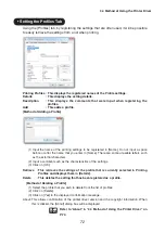
Page 72: ...the name that you enter in Name There are some unusable letters such as the external characters 2 Input a comment such as the characteristics of the settings 3 Click on OK Retrieve This retrieves the...

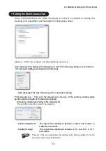
Page 73: ...sets the timing of the automatic cleaning Print Adjustment This sets the adjustment amounts of the printing leading edge position and the length of the data to be printed Carrying out Settings relati...

Page 74: ...med Setting the Utility Tab Using the Utility tab confirmation of the printer setting information whether or not the display is shown the auto off setting and the print mode setting can be carried out...

Page 75: ...driver Review Mode This allows switching on and off the printer Review mode Off The contents of the data received by the printer are not shown on the display On The contents of the data received by t...

Page 76: ...nimum Top Margin 2mm Minimum Bottom Margin 2mm For printing media that has a width of 58mm or greater the top and bottom margins will be 2mm or greater In addition the printing possible area will be t...

Page 77: ...n the Printer does not become Online 82 When the Printing does not Start Communications are not possible 82 When Nothing is Printed 83 When Plates and Sheets cannot be Fed Normally 83 When the Printed...

Page 78: ...possible to set the setting times None 5 min later 10 min later 30min later 1 Press the Menu key 2 Press the Menu key or key to change the Menu items Menu An Auto off is displayed 3 Press the Enter ke...

Page 79: ...selected item e g Menu English 4 Press the Enter key to make the setting To Increase the Printing Speed Print Mode Menu Print Mode By selecting the Speed option 60mm sec it will be possible to make t...

Page 80: ...auto cleaning will be implemented after the printing has finished For this reason in cases such as sheet printing where a large amount of printing is carried out continuously there may be differences...

Page 81: ...ion is displaced The vertical line of the left border is missing Leading Edge Carry out fine adjustment of this dimension A B C D E Refer to When the Printing Position is Displaced of 4 2 Troubleshoot...

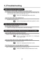
Page 82: ...display When the Printing does not Start Communications are not possible Has the USB cable been properly connected Properly connect the printer with the PC using the USB cable Reference Refer to Conn...

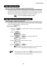
Page 83: ...tion where a plate has become jammed in the printer remove the plate using the following procedure in the Remove mode Remove Mode Menu Remove 1 Press the Online key to set the printer to Offline The o...

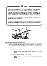
Page 84: ...ng out the printing In the case where the roll sheet has become jammed so that the roller is contacting nipping the sheet eliminate the problem by switching the Power switch between off and on to carr...

Page 85: ...ette 4 Peel off the cleaning tape that has become wound around the cleaning roller 5 Wind in the cleaning tape by turning it in the direction shown by the arrow Peel off the cleaning tape that has bec...

Page 86: ...r to 4 4 Routine Cleaning on P 94 Has an adequate ejection space been secured for the printing object If there are objects in the neighborhood of the ejection port which interfere with the ejection of...

Page 87: ...g take care of the plate storage Reference Refer to 4 5 Plate Cleaning and Storage on P 98 Setting Direction Printing Surface When there is Horizontal Streaking on the Printed Item Is there soiling of...

Page 88: ...the Printer Driver on P 64 Position Adjustment Mode Menu Position Adjustment 1 Press the Online key to set the printer to Offline The online lamp will switch off 2 Press the Menu key Menu Auto Cleani...

Page 89: ...4 Press the Enter key to enter the Length Adjustment mode 5 Press the Menu key or key to make the setting in the range between 5 0 to 0 no correction to 5 0 The length adjustment can be set in units o...

Page 90: ...ter and printing again When the Print Image is Unreadable Has the printing density been set too high If printing is carried out with the Density setting of the Advanced Settings in the printing settin...

Page 91: ...cted Has the plate or sheet become jammed In the situation where the plate or sheet has become jammed in the printer remove it using the Remove mode Reference Refer to Has the plate or sheet become ja...

Page 92: ...e cleaning tape is jammed remove the jammed tape Refer to 2 3 Setting the Cleaning Cassette on P 25 Refer to When the Printed Items are not Ejected of 4 2 Troubleshooting on P 91 Replace Ribbon Casset...

Page 93: ...much Black area in Image High black rate printing data such as black filled characters have been sent when carrying out printing using the feeder Send the correct printing data Test print not work in...

Page 94: ...should be taken out and cleaned Menu Cleaning Mode The cleaning roller is incorporated to clean off dust and dirt attached to plates and sheets before printing Use the menu cleaning mode depending on...

Page 95: ...gonally in the rightwards direction Cleaning Roller 3 Wipe the surface of the cleaning roller with a soft cloth that has been moistened with water and tightly wrung to clean off dust and dirt At this...

Page 96: ...aning set the roller after it has completely dried The cleaning roller is a consumable product In the situation where there is no cleaning effect even after cleaning the roller replace the roller As a...

Page 97: ...nd dirt When cleaning the print head adequate care should be taken If the print head is rubbed with a hard metallic object or with an object that has metal dust attached scratches will be caused and p...

Page 98: ...ust and dirt situation In situations where there are large amounts of dust or dirt clean the plates with a soft cloth moistened with water before setting them in the printer 1 Confirm that the plates...

Page 99: ...place to avoid bending and warping from occurring Ensure that roll sheets are not bent along the folds and that their forms are not damaged Maintain a temperature in the storage location between 5 C a...

Page 100: ...to Offline The online lamp will switch off 2 Press the Menu key Press the Menu key or key to change the Menu items Menu Test Print is displayed 3 Press the Enter key e g Test Print Acrylic 4 Press the...

Page 101: ...Chapter 5 Appendix In this chapter an explanation is given of the main specifications of the printer 101 5 1 Main Specifications 102 5 2 Index 103...

Page 102: ...parately Interface Conforming with USB 2 0 Full speed Operating Environment 15 to 32 5 C 10 to 85 Humidity should be non condensing Storage Environment 5 to 35 C 10 to 90 Humidity should be non conden...

Page 103: ...venient functions 78 Copies 21 65 Copy print 62 Cover 15 D Delete 55 68 Density 21 70 Display 19 21 Display lamps 19 F Feeding 65 Feeding method 21 52 Feeding port 15 Feeding roller 15 97 Form name 65...

Page 104: ...21 102 Printing possible area 76 Printing speed 79 Printing stop 55 Profiles tab 72 R Receive message 19 Ribbon cassette 29 Ribbon slackness 29 Roll holding rollers 16 36 Roll sheets 35 38 Routine cle...

Page 105: ...PUB 4Y5 8173 020 0605CP0 03 Nisca Corporation 2012...

Reviews: