MAX32600 User’s Guide
Communication Peripherals
7.3 UART
7.3.2.1
Compact Layout Configuration
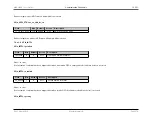
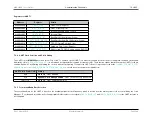
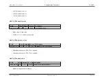
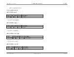
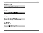
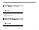
The tables below contains the available pin configurations for each of the UART ports (UART0 and UART1):
UART0
Logic Signal
Port and Pin
RX
A) P1.0 B) P2.0 D) P0.0
TX
A) P1.1 B) P2.1 D) P0.1
CTS
A) P1.2 B) P2.4 D) P0.2
RTS
A) P1.3 B) P2.5 D) P0.3
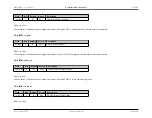
UART1
Logic Signal
Port and Pin
RX
A) P1.2 B) P2.4 D) P1.6
TX
A) P1.3 B) P2.5 D) P1.7
CTS
A) P1.6 B) P2.6
RTS
A) P1.7 B) P2.7
7.3.2.2
Standard Layout Configuration
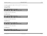
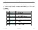
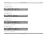
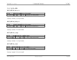
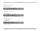
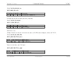
The tables below contains the available pin configurations for each of the UART ports (UART0 and UART1):
UART0
Logic Signal
Port and Pin
RX
A) P1.0 B) P2.0 C) P7.0 D) P0.0
TX
A) P1.1 B) P2.1 C) P7.1 D) P0.1
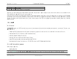
CTS
A) P1.2 B) P1.4 C) P7.2 D) P0.2
Rev.1.3 April 2015
Maxim Integrated
Page 284

