MAX32600 User’s Guide
Analog Front End
8.3 ADC
The maximum sample rate achievable that allows the ADC to sleep between samples with the PGA enabled is 180ksps and 333ksps with the PGA in bypass. High
Speed Measurement Mode leaves the ADC powered during the entire measurement window, enabling sample rates as high as 500ksps.
Both Low Power Measurement Mode and High Speed Measurement Mode support four sampling configurations. The configurations supported are:
•
Sample Mode
: The ADC measures a single input channel continuously until turned off by the CPU.
•
Burst/Decimation Mode
: A user settable number of samples are measured and optionally averaged with a configurable delay between samples.
•
Scan Mode
: Samples are taken from each configured input channel in the sequence set up by the application.
•
Scan Mode with Burst/Decimation
: A user settable number of samples are measured and optionally averaged per configured input channel before moving
to the next input channel in the sequence.
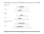
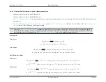
For both Low Power Measurement Mode and High Speed Measurement Mode and each of their sample configurations, there are specific equations used to achieve
a target sample rate. The sections below describe which ADC register fields are used to perform these calculations for both measurement modes and their respective
sample configurations. In addition, the equations are dependent on the PGA being either enabled or bypassed.
Decimation Filter Modes
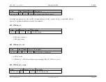
When the ADC is set to burst mode in either scan or sample modes, the ADC supports decimation filtering. The register
is used to select the
decimation filter type. A value of 0 turns off the decimation filtering and the ADC outputs the raw data samples acquired in the ADC output FIFO. A value of 1 outputs
the average of the samples taken in burst mode as specified by
. Using decimation mode affects the ADC sample rate calculations.
See Sample Rate Calculations below for details.
ADC Sample Rate Configuration Registers Base Values Table
(minimum value)
PCLK Conversion Clock Cycles
Maximum Sample Rate
1 (PGA bypassed)
N/A
9
0
0
16
500ksps
0 (PGA enabled)
1X or 2X
7
1
1
17
470ksps
0 (PGA enabled)
4X
7
1
2
18
444ksps
0 (PGA enabled)
8X
7
2
2
19
420ksps
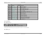
Description of Variables Used by the Sample Rate Equations
Parameter
Description / Register Location
F
TARGET
Ideal ADC sample frequency, before integer rounding of counter variables
Rev.1.3 April 2015
Maxim Integrated
Page 418


