MAX32600 User’s Guide
Analog Front End
8.3 ADC
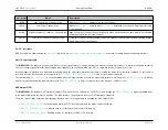
Parameter
Description / Register Location
F
S
Actual ADC Sample Frequency
F
PCLK
ADC Peripheral Clock Frequency (usually 8MHz)
pga_trk_cnt
Value in register
adc_acq_cnt
Value in register
pga_acq_cnt
Value in register
adc_brst_cnt
Value in register
N
SCAN
Value in register
PGA Bypass
Value in register
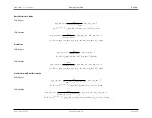
8.3.4.8.1
Sample Rate Calculation: High Speed Measurement Mode
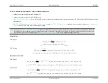
• 500ksps maximum sample rate with PGA bypassed
• 470ksps maximum sample rate with PGA enabled
• Sample rate is set using the
register field
•
and
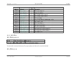
register fields should be set to the values shown in
based
on the PGA mode and PGA gain setting
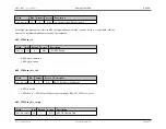
Note
Since the
register field requires an integer value, it is necessary to round up or down the result of the equations below. To determine the
best setting to achieve the target sample rate, it is advised to calculate F
S
using both the rounded up and rounded down values and decide which
results in the optimum value for
to meet the application target frequency.
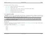
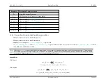
Sample Mode
PGA Bypass
pga
_
trk
_
cnt
=
f
target
f
PCLK
−
adc
_
acq
_
cnt
−
7
f
S
= (
pga
_
trk
_
cnt
+
adc
_
acq
_
cnt
+
7
)
×
f
PCLK
PGA Enabled
pga
_
trk
_
cnt
=
f
target
f
PCLK
−
pga
_
acq
_
cnt
−
adc
_
acq
_
cnt
−
8
f
S
= (
pga
_
trk
_
cnt
+
pga
_
acq
_
cnt
+
adc
_
acq
_
cnt
+
8
)(
f
PCLK
)
Rev.1.3 April 2015
Maxim Integrated
Page 419

