


MAX32600 User’s Guide
System Configuration and Management
4.1 Power Ecosystem and Operating Modes
Field
Bits
Default
Access
Description
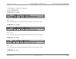
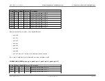
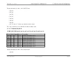
gpio11
11
0
R/O
Wake-Up Detect Status for P1.3
gpio12
12
0
R/O
Wake-Up Detect Status for P1.4
gpio13
13
0
R/O
Wake-Up Detect Status for P1.5
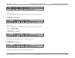
gpio14
14
0
R/O
Wake-Up Detect Status for P1.6
gpio15
15
0
R/O
Wake-Up Detect Status for P1.7
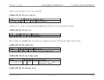
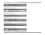
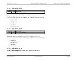
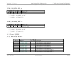
Displays wakeup detection status of the 8 listed GPIO pads,
• bit 0: Px.0
• bit 1: Px.1
• bit 2: Px.2
• bit 3: Px.3
• bit 4: Px.4
• bit 5: Px.5
• bit 6: Px.6
• bit 7: Px.7 where a ’1’ bit represents a wakeup condition detected.
Bits for any I/O pads that are not in Wakeup Detect Mode will always read 0.
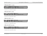
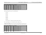
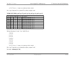
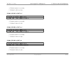
PWRMAN_WUD_SEEN0.[gpio16, gpio17, gpio18, gpio19, gpio20, gpio21, gpio22, gpio23]
Field
Bits
Default
Access
Description
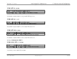
gpio16
16
0
R/O
Wake-Up Detect Status for P2.0
gpio17
17
0
R/O
Wake-Up Detect Status for P2.1
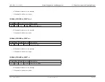
gpio18
18
0
R/O
Wake-Up Detect Status for P2.2
gpio19
19
0
R/O
Wake-Up Detect Status for P2.3
gpio20
20
0
R/O
Wake-Up Detect Status for P2.4
gpio21
21
0
R/O
Wake-Up Detect Status for P2.5
Rev.1.3 April 2015
Maxim Integrated
Page 55