


MAX32600 User’s Guide
Analog Front End
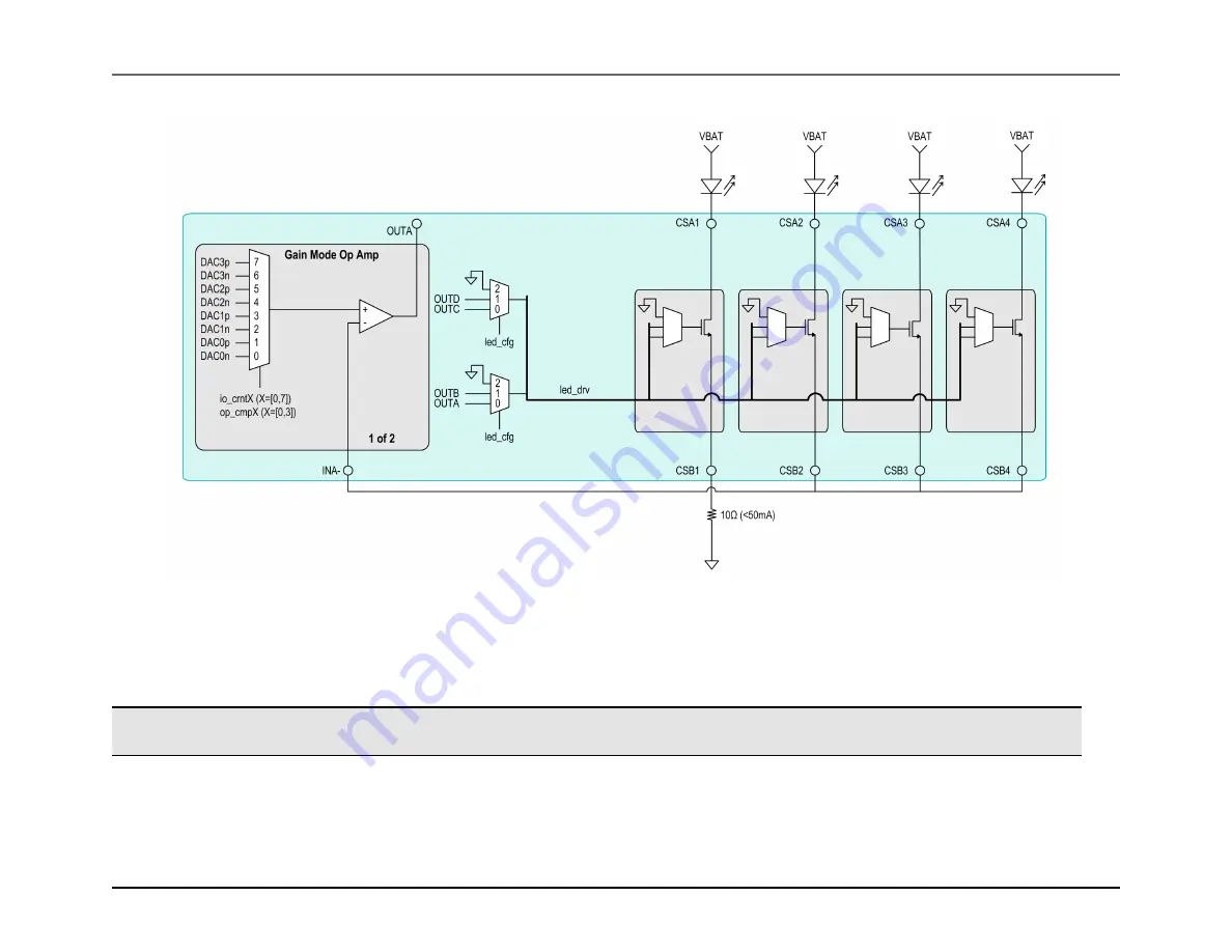
8.5 LED
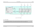
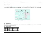
Figure 8.10: LED Block Diagram
8.5.2
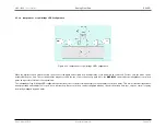
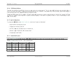
LED Configuration
Note
In each block diagram below, integrated components are rendered in black and external components are depicted in grey boxes. Also, in configura-
tions with more than one LED, current is not necessarily run simultaneously; internal switches are used to manage current.
Rev.1.3 April 2015
Maxim Integrated
Page 472