MAX32600 User’s Guide
Analog Front End
8.3 ADC
8.3.4.8.2
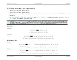
Sample Rate Calculation: Low Power Measurement Mode
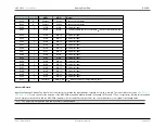
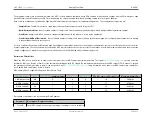
• 180ksps maximum sample rate with PGA enabled
• 333ksps maximum sample rate with PGA bypassed
•
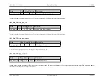
is the register field used to set the target sample rate and controls the number of PCLKs that the ADC will sleep after each
measurement
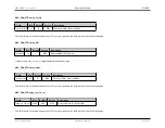
•
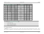
, and
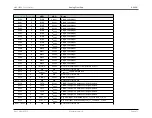
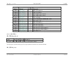
should be set to the values shown in
based on the PGA mode and PGA gain setting
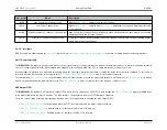
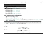
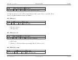
Note
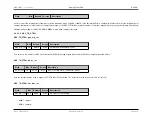
Since the
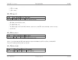
requires an integer value, it is necessary to round up or down the result of the equations below. To
determine the best setting to achieve the target sample rate, it is advised to calculate F
S
using both the rounded up and rounded down values and
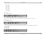
decide which results in the optimum value for
to meet the application target frequency.
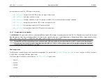
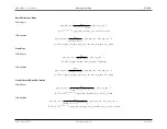
Sample Mode
PGA Bypass
adc
_
sl p
_
cnt
=
f
target
f
PCLK
−
adc
_
acq
_
cnt
−
24
f
S
= (
adc
_
acq
_
cnt
+
adc
_
sl p
_
cnt
+
24
)
×
f
PCLK
PGA Enabled
adc
_
sl p
_
cnt
=
f
target
f
PCLK
−
pga
_
trk
_
cnt
−
pga
_
acq
_
cnt
−
adc
_
acq
_
cnt
−
40
f
S
= (
pga
_
trk
_
cnt
+
pga
_
acq
_
cnt
+
adc
_
acq
_
cnt
+
adc
_
sl p
_
cnt
+
40
)
×
f
PCLK
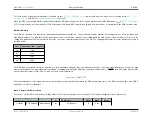
Burst/Decimation Mode
PGA Bypass
adc
_
sl p
_
cnt
=
f
target
f
PCLK
−
(
2
adc
_
brst
_
cnt
−
1
)(
pga
_
trk
_
cnt
+
adc
_
acq
_
cnt
+
7
)
−
adc
_
acq
_
cnt
−
24
f
S
= (
2
adc
_
brst
_
cnt
−
1
)(
pga
_
trk
_
cnt
+
adc
_
acq
_
cnt
+
7
) +
adc
_
sl p
_
cnt
+
adc
_
acq
_
cnt
+
24
×
f
PCLK
PGA Enabled
adc
_
sl p
_
cnt
=
f
target
f
PCLK
−
2
adc
_
brst
_
cnt
×
(
pga
_
trk
_
cnt
+
pga
_
acq
_
cnt
+
adc
_
acq
_
cnt
+
8
)
−
32
f
S
=
2
adc
_
brst
_
cnt
×
(
pga
_
trk
_
cnt
+
pga
_
acq
_
cnt
+
adc
_
acq
_
cnt
+
8
) +
adc
_
sl p
_
cnt
+
32
×
f
PCLK
Rev.1.3 April 2015
Maxim Integrated
Page 421

