MAX32600 User’s Guide
System Configuration and Management
4.1 Power Ecosystem and Operating Modes
Reference
below for a more detailed description of the power I/O.
4.1.6
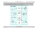
Power Manager
The Power Manager monitors and distributes the three main voltage rail inputs (V
BUS
, V
DD
, and V
RTC
) on the
MAX32600
. The analog power domain inputs (V
DDA3ADC
,
V
DDA3DAC
, and V
DDA3REF
) are separate pins that allow the user to provide external isolation from each domain. The V
DDA3
analog power output can be shorted to
any/all of the analog power domain inputs or optionally connected through filtering networks for isolation. In addition to power distribution and management, the
Power Manager monitors power levels using several Supply Voltage Monitors (SVMs) and Power-On Resets (PORs). SVM warning levels are programmable (see
section
Supply Voltage Monitoring During LP0: STOP and LP1: STANDBY
for details). POR levels are not changeable and are set at the factory per the
MAX32600
data sheet.
4.1.7
Power Sequencer
The Power Sequencer controls the
MAX32600
during
Low Power Modes (LP0: STOP and LP1: STANDBY)
. When LP0: STOP and LP1: STANDBY are exited, the
Power Sequencer transfers control to the system manager and the part enters either LP2: PMU or LP3: RUN. One of the primary functions of the Power Sequencer
is to ensure power, clocks, and resets are stable prior to transitioning the system to either LP2: PMU or LP3: RUN. During LP0: STOP and LP1: STANDBY, wakeup
interrupts are continuously monitored while consuming very little power. Once an interrupt event occurs, the Power Sequencer automatically enables SVMs as well
as active LP2: PMU and LP3: RUN peripherals, including the internal 1.8V regulator and the 24MHz Relaxation Oscillator.
When the Power Sequencer determines the power, clocks, and resets are valid, the clock gating circuitry is disabled and the
MAX32600
is allowed to enter LP2:
PMU or LP3: RUN.
4.1.7.1
Power Mode Transitioning to Low Power Modes
To take full advantage of the low power modes of operation in the
MAX32600
, application firmware will need to spend as much time as possible in either LP0: STOP
and LP1: STANDBY modes. Prior to entering these modes, it is extremely important to set up the wakeup interrupts and supply voltage monitor configuration. To
enter LP0: STOP, reference section
Entering LP0: STOP or LP1: STANDBY
above.
4.1.7.2
Supply Voltage Monitoring During LP0: STOP and LP1: STANDBY
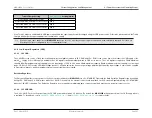
During LP0: STOP or LP1: STANDBY modes, the Power Sequencer can be set to monitor the Supply Voltage Monitors (SVM) periodically. Periodic monitoring
enables the system to check to ensure power is adequate at a specific interval and reduces overall system power significantly. To enable periodic monitoring, set the
field
to a desired count value and enable one or more SVMs during LP0: STOP or LP1: STANDBY modes.
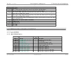
SVM Options for LP0 / LP1
Description
Enable Field
V
DD
3V Main Supply
Rev.1.3 April 2015
Maxim Integrated
Page 38

