MAX32600 User’s Guide
System Clock, Timers/Counters, Watchdog Timers and Real Time Clock
10.4 Timers/Counters
Timer Port and Pin Configurations
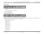
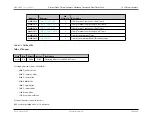
The table below contains the available pin configurations for the four timers (TMR0, TMR1, TMR2, and TMR3):
Note
See
Pin Configurations, Packages, and Special Function Multiplexing
for a detailed mapping of
MAX32600
multiplexed function locations and priority
distinction. Timer modules interface with the GPIO pins, which claim the lowest functional priority (see
GPIO Pins and Peripheral Mode Functions
for further information).
GPIO Function
Port and Pin
TMR0-3
P0.0-7 P1.0-7 P2.0-7 P6.0-7 P7.0-7
10.4.2
32-bit Mode Timer Operation
The timers are 32-bit up-counter timers. Use
to configure the operating control register for the timer mode. Additional mode information is found
below.
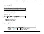
Minimum time-out delay is set by:
• Loading the value 0x0000_0001 into the Timer Compare register,
• Setting the prescale value to 1 in the
field
Maximum time-out delay is set by:
• Loading the value 0x0000_0000 into the Timer Compare register,
• Setting the prescale value to 4096 in the
field
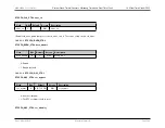
If the timer reaches 0xFFFF_FFFF, the timer rolls over to 0x0000_0000 and continues counting.
The current count value,
, in the timers can be read while the timer is counting and enabled. This read action does not affect the timer’s operation.
As a rule, the timer output is toggled every time the counter is reloaded.
10.4.2.1
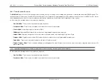
One-Shot Mode
In One-Shot mode, the timer counts from the start count value stored in the
up to the 32-bit Compare value stored in the
. Upon
reaching the Compare value, the timer generates an interrupt and the count value in the Timer register is reset to 0x0000_0001. Then, the timer is automatically
Rev.1.3 April 2015
Maxim Integrated
Page 588

